Tray for producing particulate food products
Active Publication Date: 2008-01-08
DIPPIN DOTS INC
173 Cites 7 Cited by
AI-Extracted Technical Summary
Problems solved by technology
Unfortunately, liquid particles or specks are sometimes released from the trays, which results in the formation of frozen fragments.
The fragments are not only undesirable in appearance...
Method used
[0014]The cryogenic processor 10 includes a freezing chamber 12 that is most preferably in the form of a conical tank that holds a liquid refrigerant therein. The freezing chamber 12 incorporates an inner shell 14 and an outer shell 16. Insulation 18 is disposed between the inner shell 14 and outer shell 16 in order to increase the thermal efficiency of the chamber 12. Vents 20 are provided to ventilate the insulated area formed between the shells 14 and 16. The freezing chamber 12 is a free-standing unit supported by legs 22. Alternatively, the freezing chamber 12 may be disposed in a frame that is specially built to support the processor while in use.
[0028]As stated, it has been determined that the projections 44 having a length of at least 0.75 inches create less broken beads and unwanted fragments. Vacuum molded plastic trays can be manufactured to have these lengths for projections, but such plastic trays wear out more quickly and cannot withstand the high temperature cleaning cycles. It is thus desired to make the trays out of a heavier, more durable substance such as stainless steel. Steel trays are more durable, but manually welding steel trays is both painstaking and time-consuming. One solution to this is to use threaded pipettes for the projections, which can be screwed into a tray and then welded. Such threaded combinations assists in more consistent welds. However, such threaded assemblies do not conform to USDA 3A standards for food production, because contaminants can work their way into the threaded surfaces which are not removable by cleaning processes. Also, the surfaces of the threads may adhere inconsistently, so that any sugars within the food products passed therethrough can work their way inside the threaded surfaces and cause oxidization and premature wear on the projections 44.
[0032]The computerized welding insures uniform penetration and no burn through as well as is less expensive due to lower hand labor involved. It is possible for good results to be obtained by hand welding but highly unlikely that a human could weld 500 or more projections 44 flawlessly with no craters or pits that would allow bacteria to settle. The projections 44 can be ...
Benefits of technology
[0005]It is a further object of the present invention is to provide each of the plurality of projections being aligned in fluid communication with one of the plurality of orifices in the bottom wall of th...
Abstract
A tray assembly for use in feeding liquid composition to a freezing chamber is disclosed. The tray has a plurality of projections that are designed to provide regulated discharge of the liquid composition from the tray and to feed the liquid composition into the freezing chamber in uniformly sized drops. The projections area each downwardly disposed in relation to the tray. The tray has a bottom wall with a plurality of orifices, where each orifice is associated with a corresponding projection. These projections are uniform in size and can be formed using computerized welding techniques. An alternate embodiment in which the tray is pressurized is also disclosed.
Application Domain
Lighting and heating apparatusIce production +6
Technology Topic
Freezing chamberLiquid composition +5
Image
Examples
- Experimental program(1)
Example
[0012]Having summarized various aspects of the present invention, reference will now be made in detail to the description of the invention as illustrated in the drawings. While the invention will be described in connection with these drawings, there is no intent to limit it to the embodiment or embodiments disclosed therein. On the contrary, the intent is to cover all alternatives, modifications and equivalents included within the spirit and scope of the invention as defined by the appended claims.
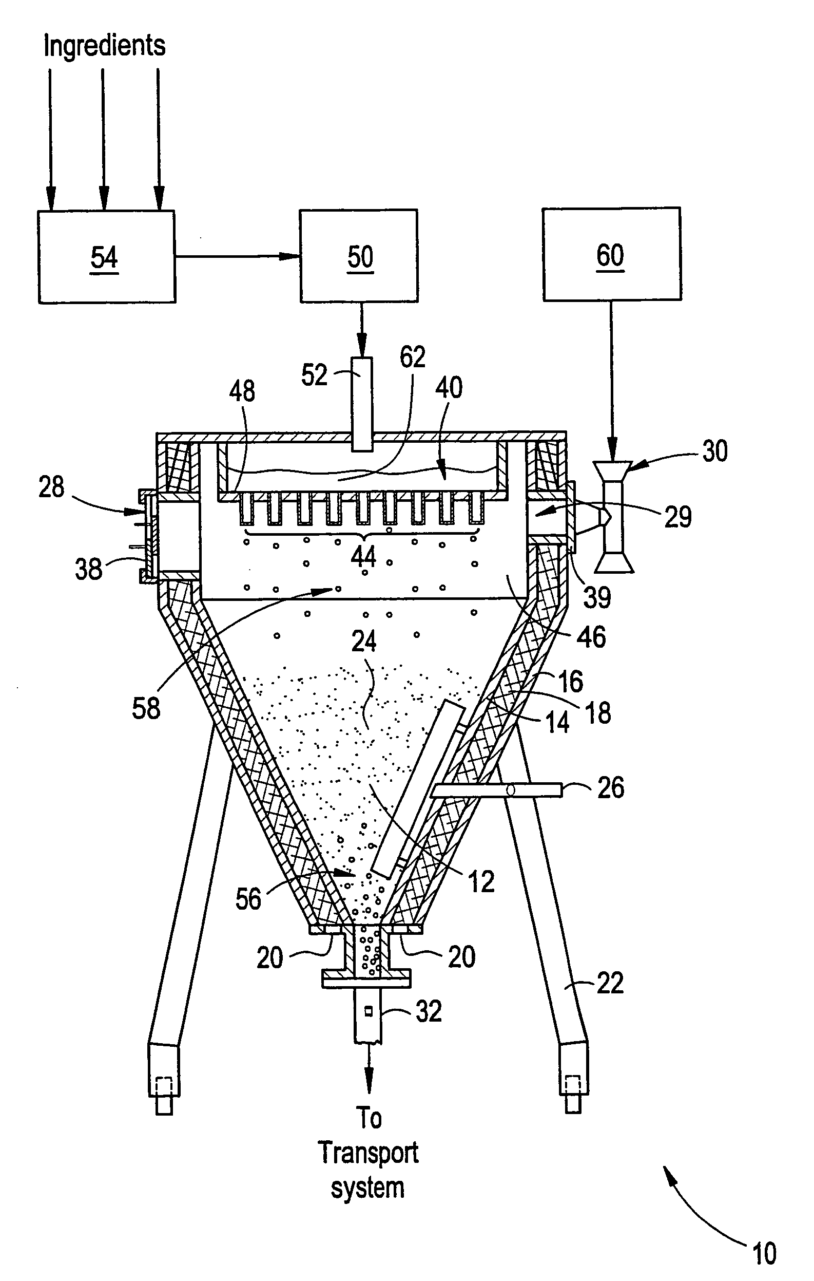
[0013]FIG. 1 shows a cryogenic processor constructed in accordance with the preferred embodiment of the present invention to produce free-flowing frozen food products in the form of small beads. The fundamental method utilized to produce the product is described in detail in U.S. Pat. No. 5,126,156.
[0014]The cryogenic processor 10 includes a freezing chamber 12 that is most preferably in the form of a conical tank that holds a liquid refrigerant therein. The freezing chamber 12 incorporates an inner shell 14 and an outer shell 16. Insulation 18 is disposed between the inner shell 14 and outer shell 16 in order to increase the thermal efficiency of the chamber 12. Vents 20 are provided to ventilate the insulated area formed between the shells 14 and 16. The freezing chamber 12 is a free-standing unit supported by legs 22. Alternatively, the freezing chamber 12 may be disposed in a frame that is specially built to support the processor while in use.
[0015]A refrigerant 24, preferably liquid nitrogen in view of its known freezing capabilities, enters the freezing chamber 12 by means of refrigerant inlet 26. The refrigerant 24 entering chamber 12 through inlet 26 is used to maintain a predetermined level of liquid refrigerant in the freezing chamber and must be added to replace refrigerant 24 that is lost by evaporation or by other means incidental to production. Any gaseous refrigerant that has evaporated from the surface of the liquid refrigerant 24 in freezing chamber 12 primarily vents to the atmosphere through exit port 29 which cooperates with the vacuum assembly 30, which can be in the form of a venturi nozzle. Extraction of the frozen beads occurs through the product outlet 32 adapted at the base of the freezing chamber 12.
[0016]An ambient air inlet port 28 with adjustment doors 38 and exit port 29 with adjustment doors 39 are provided to adjust the level of gaseous refrigerant which evaporates from the surface of the liquid refrigerant 24 so that excessive pressure is not built up within the processor 10 and freezing of the liquid composition in the feed assembly 40 does not occur.
[0017]As shown in FIG. 1, a feed tray 48 receives liquid composition 62 from a delivery source 50. Typically, a pump drives the liquid composition 62 through a delivery tube 52 into the feed tray 48. A premixing device 54 allows several compositions, not all of which must be liquid, such as powdered flavorings or other additives of a size small enough not to cause clogging in the feed assembly 40, to be mixed in predetermined concentrations for delivery to the feed tray 48.
[0018]In order to create uniformly sized beads 56 of frozen food products, uniformly sized droplets 58 of liquid composition are required to be fed through gas diffusion chamber 46 to freezing chamber 12. The feed tray 48 works with the feed assembly 40 to form droplets 58 of the desired character. When the droplets 58 of liquid composition contact the refrigerant vapor in the gas diffusion chamber 46, beads 56 that are formed which fall to the bottom of chamber 12. A transport system connects to the bottom of chamber 12 at outlet 32 to carry the beads 56 to a packaging and distribution network for later delivery and consumption.
[0019]A vacuum assembly 30 cooperates with air inlet 28 and adjustment doors 38 so that an ambient air flow passes through the inlet and around feed assembly 40 to ensure that no liquid composition freezes therein. This is accomplished by mounting the vacuum assembly 30 and air inlet 28 on opposing sides of the gas diffusion chamber 46 such that the incoming ambient air drawn by the vacuum assembly 30 is aligned with the feed assembly. In this configuration, ambient air flows around the feed assembly warming it to a sufficient temperature to inhibit the formation of frozen liquid composition in the feed assembly flow channels. Air source 60, typically in the form of an air compressor, is attached to vacuum assembly 30 to provide appropriate suction to create the ambient air flow required.
[0020]FIG. 1 also shows a substantially rectangular tray 48 positioned above the freezing chamber 12 and extending completely across the top of the freezing chamber 12 along its minor dimension. However, the assembly 10 can have a very large tray 48 constructed to cover the entirety of the freezing chamber 12 or, alternatively, smaller trays 48 may be manufactured and placed side by side. In either case, in order to create uniformly sized beads 56 of frozen product, uniformly sized droplets 58 of liquid composition 62 are required to be fed to the freezing chamber 12. Accordingly, the tray 48 is designed to form droplets 58 of the desired character.
[0021]As shown in FIG. 2, the tray 48 preferably has a bottom surface and side walls which form an enclosure for receiving the liquid composition 62 from a source 34. Typically, a pump drives the liquid composition 62 through a delivery tube 52 into the tray 48. The liquid composition 62 is then fed to the freezing chamber 12 as is more fully discussed below.
[0022]As shown in FIG. 2, the bottom wall of the tray 48 is formed with a plurality of orifices which connect to projections 44. Preferably, the orifices are in an ordered array of rows and columns, although the present invention should not be considered as limited exclusively thereto. The liquid composition 62 flows into and through the orifices within the tray 48 in the direction of the freezing chamber 12 (usually downward) during the production process.
[0023]The projections 44 preferably extend downwardly from the bottom wall 30 of the tray 28 toward the freezing chamber 12. As shown in FIG. 3, each projection 44 thus has, at its first end 66, an inlet opening that is in communication with the associated orifice and, at its second end 68, an outlet opening. A flow channel extends the entire length of each projection 44 from the inlet opening 66 to the outlet opening 68.
[0024]The projections 44 can be cylindrical and uniform in cross-section, but can also taper to become narrower toward their second end 68 if desired. For purposes of illustration, FIGS. 1, 2, and 3 depict cylindrical, non-tapered projections 44 which can be more widely available than tapered projections. Where the projections 44 are tapered, the inlet opening has a larger dimension than the outlet opening. Such narrowing of the flow channel 54 promotes regulated accumulation of the liquid composition 20 within the flow channel of the projection 44 and thus promotes regulated discharge of the liquid composition from the tray 28.
[0025]Another way to promote regulated accumulation within the flow channel of the projection 44 is to fabricate the projection 44 to be at least 0.75 inches long. In either case, this design further allows a droplet 58 to be formed in orderly fashion until the net gravity force overcomes the interfacial tension forces on the droplet 58 and it falls toward the freezing chamber 12.
[0026]Droplets released from prior art orifices sometimes break apart into smaller droplets 58, creating fragmented beads 56 of widely varying sizes and also resulting in further spattering. Undersized beads 56 distract from the unique and pleasing appearance of the more desirably sized beads 56 and thus it is desired to eliminate them from the final product where possible. Furthermore, the spattering created during droplet release and/or break-up generates minute particles that also fall into the freezing chamber 12 and form particles of frozen microbeads that accumulate at the bottom of the freezing chamber 12. This creates the need to shut the production process down to clean out the freezing chamber 12. Furthermore, the frozen microbeads represent wasted mix 62.
[0027]To overcome these and other problems, the projections 44 of the present invention promote the regulated discharge of the liquid composition from the tray 48 and the formation of more uniformly sized droplets 58 of liquid composition 20 that, when delivered to the freezing chamber 12, form more uniformly sized beads 56 of frozen product. In addition, the projections 44 reduce the spattering of minute particles of liquid composition 20 and thus reduce the formation of frozen dust that has previously accumulated at the bottom of the freezing chamber 12.
[0028]As stated, it has been determined that the projections 44 having a length of at least 0.75 inches create less broken beads and unwanted fragments. Vacuum molded plastic trays can be manufactured to have these lengths for projections, but such plastic trays wear out more quickly and cannot withstand the high temperature cleaning cycles. It is thus desired to make the trays out of a heavier, more durable substance such as stainless steel. Steel trays are more durable, but manually welding steel trays is both painstaking and time-consuming. One solution to this is to use threaded pipettes for the projections, which can be screwed into a tray and then welded. Such threaded combinations assists in more consistent welds. However, such threaded assemblies do not conform to USDA 3A standards for food production, because contaminants can work their way into the threaded surfaces which are not removable by cleaning processes. Also, the surfaces of the threads may adhere inconsistently, so that any sugars within the food products passed therethrough can work their way inside the threaded surfaces and cause oxidization and premature wear on the projections 44.
[0029]To solve these and other problems, computerized welding techniques which create the weld by a lower temperature, higher precision fusion process can reduce these obstacles yet still accommodate the heavier tray materials. To that end, FIG. 4 shows an exemplary computer screen from a computerized welding software program. Using such a computer design mechanism, the desired welds can be first set up in software and then implemented by an automated welding process that has no human intervention but instead receives and is directed by a software program which interprets information from the computer screen shown in FIG. 4. This is advantageous because computerized fusion welds achieve greater accuracy than manual welds. Also, traditional welds have the problem of impurities and crud working their way into the weld thereby making the welded surface uneven, pocked or pitted, subject to breakage, and inconsistent in size. Because the tray 48 of the present invention may be used to make millions of beads 56 or other commercial food products every day, exact consistency of the projection 44 and flow channel therein is crucial. All projections 44 and corresponding flow channels must be exactly the same size. This consistency can be difficult and time-consuming to achieve with manual welds. However, computerized welding techniques lend themselves well to achieving this desired accuracy.
[0030]The CAD drawing of a welding tray 48 shown in FIG. 4 provides specifications for a computerized fabrication mechanism. An operator can specify the type of weld, the technique used and the tolerances and finished appearance, i.e. buffed to 400 grit, to meet USDA 3A standards. Although not entirely shown in FIG. 4, there can be more than 500 projections 44 in a single tray 48. However, the actual number of projections 44 is not as important as their spacing, so that droplets 58 do not touch each other when falling into the vacuum chamber 12. This can result in forming clumps of beads 56 as the droplets 58 freeze, which is highly undesired.
[0031]The process used in the welding of the tray 48 can be an electron beam weld done in a vacuum chamber. This type of accuracy could also be performed by laser weld with a shielded gas or by gas tungsten arc weld (GTAW). The electron beam provides accuracy in penetration depth of the stainless material from which the tray 48 is formed. In a preferred embodiment, the entire welding process is controlled by computer with no human intervention. However, the tray 48 of the present invention could also be successfully achieved if done by a highly skilled welder. The main criteria is that the welded projections 44 meet USDA 3A standards for dairy equipment. Standards for dairy are different than from normal foods or FDA standards, in that dairy standards are more strict. The USDA 3A standard is generally accepted all over the world as a standard of safety for food producing equipment.
[0032]The computerized welding insures uniform penetration and no burn through as well as is less expensive due to lower hand labor involved. It is possible for good results to be obtained by hand welding but highly unlikely that a human could weld 500 or more projections 44 flawlessly with no craters or pits that would allow bacteria to settle. The projections 44 can be straight rather than tapered to be able to use readily available material off the shelf although tapered projections are acceptable also. The diameter and length of the projections 44 are important factors in that they govern the flow rate and the uniformity of the beaded product.
[0033]The present invention is easier to clean not only with detergents and sanitizers in a conventional cleaning in place (CIP) system, but can also be steam sterilized or autoclaved. One problem with plastic pipettes is that they sometimes fall into the freezing chamber 12 and then get mixed in within the beads 56. Being plastic, the broken pipettes could not be detected with metal detectors and were thus difficult to account for.
[0034]FIG. 5 shows another embodiment of the present invention involving an enclosed tray 148 that can have a pulse pump 180 feeding it to produce a precise dosing action. In this embodiment, a stainless tray with approximately 1″ depth has a cover welded or securely sealed to the top making it totally enclosed. The ice cream mix 162 can be delivered by a piston metering (pulse) pump 180, although other types of pumps are contemplated within the spirit and scope of the present invention. Once the enclosed tray 148 is filled, the feed is metered by piston pump to a precise volume. Each time the piston strokes, exactly one drop of mix comes out each of the array of projections 44. This method produces a precisely uniform droplet each time the piston stroked. As stated, the gravity methods described earlier can result in smaller droplets 158 forming immediately after a larger droplet 158 falls. This results in unwanted smaller beads 156 which can add up to as much as 15% of the amount of the total beads 156 produced, depending on the speed at which the cryogenic processor 10 is being operated. Thus, an enclosed tray 148 and accompanying dosing system can even further reduce the percentage of fragmented beads 156 thereby creating more uniformity in the product.
[0035]The pump 180 described above could be controlled by a programmable logic controller (PLC) that would be sensitive to the pressure within the enclosed tray 148. In an exemplary embodiment, the PLC could account for the number of trays being used and calculate the volume of mix to apply to the multiple trays 148. A pressure sensor and transmitter in each tray 148 would relay information back to the PLC to alter the signal to the pump as needed.
[0036]An enclosed tray 148 would have to have slightly smaller projections 44 and flow channels than those described in FIGS. 1-4, such as a 16 or 18 gauge depending on the viscosity of the product mix 162. This would be to prevent unwanted gravitational dropping thereof. These smaller gauge projections 44 should require a pressure beyond gravitational to produce the droplet.
[0037]As stated, a positive pressure piston pump 180 would be well suited for the application, but a similar effect could also be achieved with a lobe type positive displacement pump or even a paristaltic pump. As shown in FIG. 5, a pump pressure transmitter 184 could be attached to the top of the tray 148 with the sensing unit flush with the top of the tray 148, for easy removal. The pressure transmitter 184 could be placed anywhere and be functional, but it will be best for sanitary application to insert it through the top of the tray covering, and extend up out of the processor lid. A pump feed line would be in turn attached to the pressure transmitter 184 that is attached to the top of the tray also.
[0038]It is also a desired feature of the enclosed tray 148 that the size of the projection 144 be too small for gravity to pull the droplet through keeping the tray from forming droplets until a specific amount of pressure is applied. The intermittent action of the piston pump will cause the tray to pressurize forming a droplet, and depressurize when the droplet separates from the projection. This cycling of the pump at a specific RPM will keep the flow of droplets constant. By increasing the RPM, the flow of product will increase up to a limit in which the pressure would become great enough to make the liquid stream instead of exit in droplets. The pressure transmitter 184 will send the signals back to the PLC to maintain the pressure to the correct amount to provide for optimal droplet uniformity and production capacity.
[0039]The enclosed tray 148 of the present invention could be used in other applications other than low-temperature to provide uniform droplet sizes in food preparation. One possible alternative application would be in the preparation of chocolate. Another may be in the preparation of candies.
[0040]Both trays 48 and 148 can be cleaned by attaching the pump feed line to a Clean In Place (CIP) system, which is advantageous because it does not require disassembling the entire cryogenic processor 10. The CIP system would flood the tray and create pressure to stream the cleaning solution through the projections. A velocity of 5 feet per second is required to meet federal sanitation standards.
[0041]It is anticipated that various changes may be made in the arrangement and operation of the system of the present invention without departing from the spirit and scope of the invention, as defined by the following claims.
PUM


Description & Claims & Application Information
We can also present the details of the Description, Claims and Application information to help users get a comprehensive understanding of the technical details of the patent, such as background art, summary of invention, brief description of drawings, description of embodiments, and other original content. On the other hand, users can also determine the specific scope of protection of the technology through the list of claims; as well as understand the changes in the life cycle of the technology with the presentation of the patent timeline. Login to view more.