Connection verifying device and connection verifying structure for a pipe and a connector

a verification device and connection technology, applied in the direction of hose connections, couplings, pipes, etc., can solve the problems of inner fluid leakage, insufficient sealing properties, and inability to ensure the integrity of the connection, so as to achieve stable or uniform escape resistance force and enhance the stop function

Active Publication Date: 2008-01-08
SUMITOMO RIKO CO LTD
View PDF26 Cites 63 Cited by
  • Summary
  • Abstract
  • Description
  • Claims
  • Application Information

AI Technical Summary

Benefits of technology

[0013]In order for smooth relative movement of the annular engagement projection of the pipe in one axial direction with respect to the retainer means while the pipe is in half-fitting relation with respect to the connector, it is required for the abutment finger to push the annular engagement projection thereof stably or uniformly, not incliningly. Therefore, preferably, a pair of the disengageable parts are formed in diametrically symmetrical positions of the retainer means, the connection engageable portion or the connector, while a pair of the abutment fingers are formed on diametrically symmetrical positions on the body portion so as to correspond to the disengageable parts. This configuration exerts a stable or uniform escape-resistant force on the annular engagement projection against movement of the annular engagement projection to escape the connection engageable portion of the retainer means, and thereby a stop function is enhanced.
[0014]The connection verifying device may be configured so as to be fitted to the connector by moving slidingly over the pipe. In this case, preferably the body potion is formed in C-shape or C-shape in cross-section so as to be snap-fitted on the pipe. This configuration eliminates a fear that the connection verification device is mistakenly dropped out of the pipe when moving slidingly over the pipe.

Problems solved by technology

Therefore, unless an operator takes care sufficiently to complete connection between the pipe and the connector, the inserting end portion of the pipe might not be fully inserted into the retainer holding portion of the connector housing, or the annular engagement projection might not engage with the engagement slit or the projecting engagement claw of the retainer means.
In this state, sealing property by a sealing member therebetween becomes insufficient, and as a result an inner fluid may leak out.
Therefore, the detector piece which abuts the annular engagement projection of the pipe disturbs engagement of the detector portion with the stopper portion.
However, in case of adapting this connection verifying device, when an operator finds the pipe and the connector in half-fitting relation, an operator necessarily has to halt mounting of the connection verifying device, push-insert the pipe until the pipe is correctly fitted in and connected to the connector, and then mount the connection verifying device on the connector again.
Therefore, when the pipe is in half-fitting relation with respect to the connector, it is troublesome for the operator to connect again the pipe and the connector.
In addition, it is fear in this connection verifying device that a projecting engagement claw (stop projection) of the retainer is deformed and the annular engagement projection of the pipe escapes the projecting engagement claw.
And, as only one detector piece is provided at one circumferential position, it cannot be sufficiently prevented that the annular engagement projection of the pipe which escapes the projecting engagement claw of the retainer further moves in a direction of escaping the connector.
Thus, secure stop function cannot be expected of this connection verifying device.

Method used


Image

  • Connection verifying device and connection verifying structure for a pipe and a connector
  • Connection verifying device and connection verifying structure for a pipe and a connector
  • Connection verifying device and connection verifying structure for a pipe and a connector

Examples


Embodiment Construction

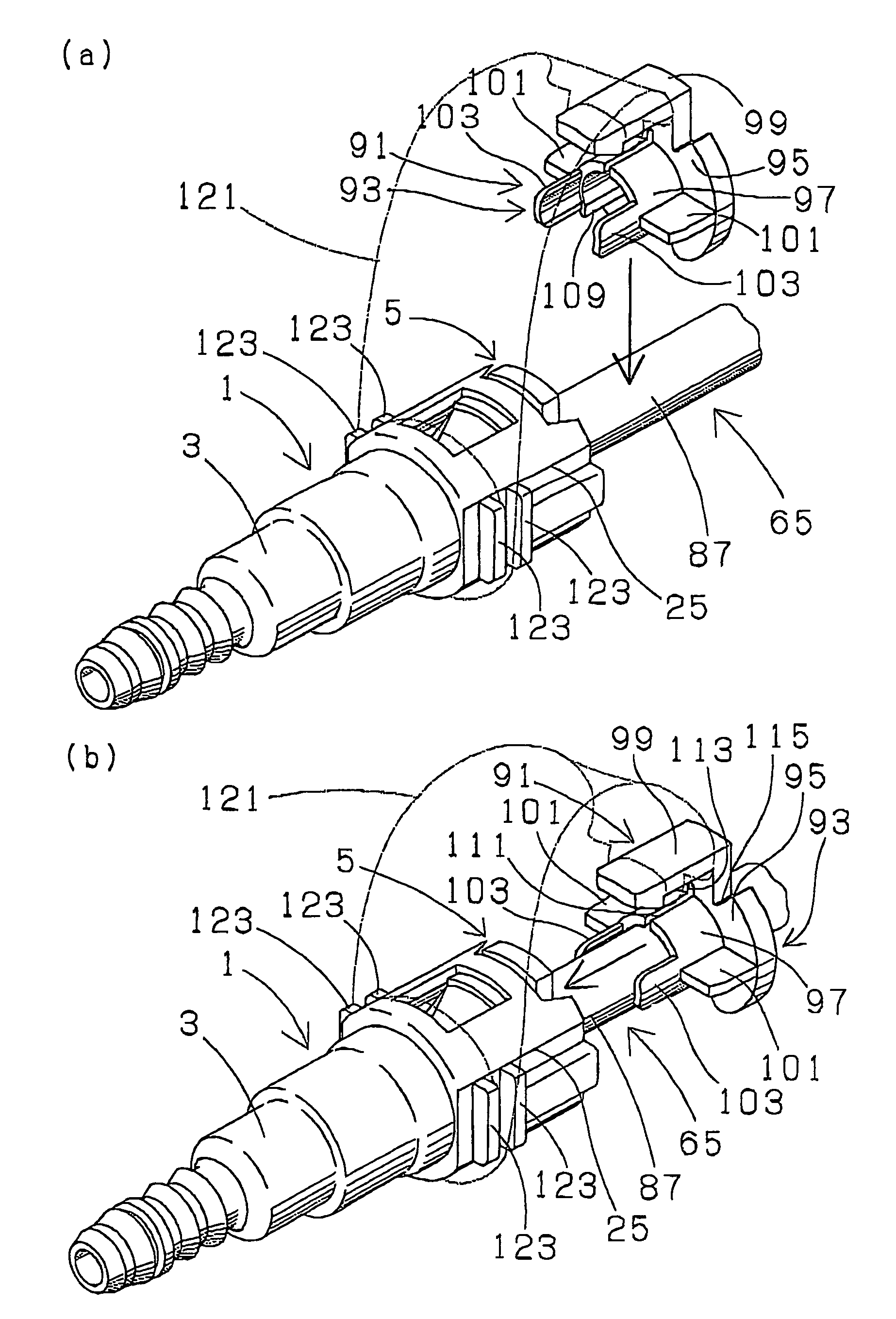
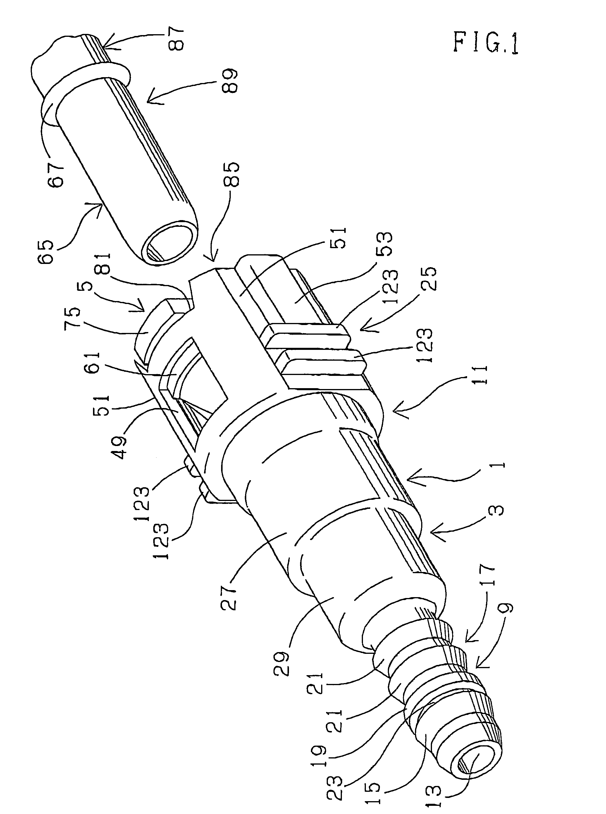
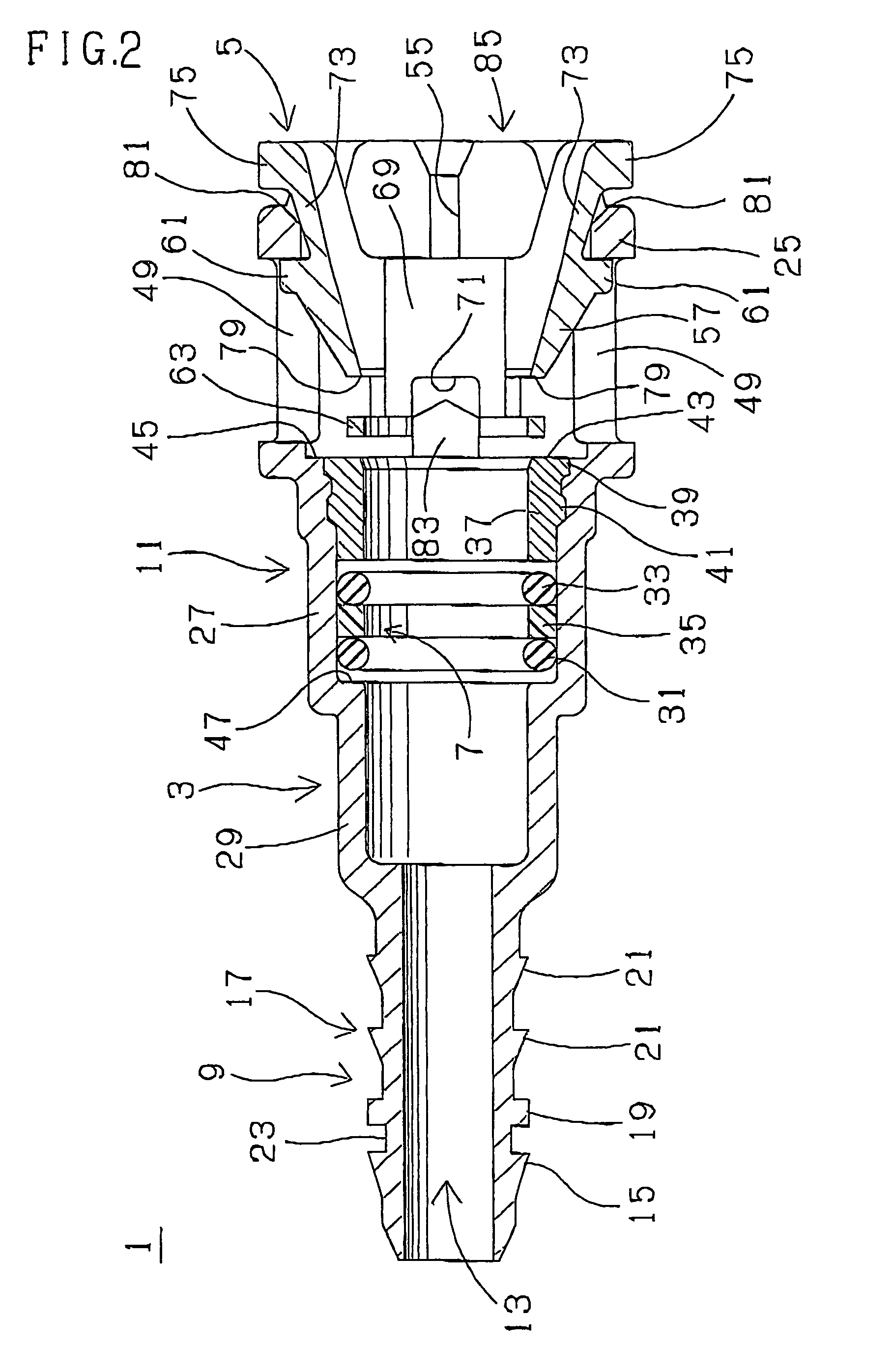
[0049]A first connection verifying structure for a pipe and a connector according to the present invention is explained with reference to FIGS. 1 to 11.

[0050]A first quick connector 1, which is adapted for assembly in a gasoline fuel piping of an automobile and adapted in the first connection verifying structure, for example, made of resin, comprises a tubular connector housing 3, a generally annular retainer 5 (retainer means) and seal means 7. The connector housing 3 made of glass fiber reinforced polyamide (PA·GF), as well shown in FIGS. 1 and 2, integrally comprises a cylindrical resin tube connecting portion 9 on an end of the connector housing 3 (one end along an axis of a quick connector 1 or a connector housing 3) and a generally cylindrical pipe inserting portion 11 on the other end thereof (the other end along the axis of the quick connector 1 or the connector housing 3), and is provided with a through-bore 13 through from one end to the other end thereof. The resin tube c...


PUM


Abstract

Connection verifying device for a pipe and a connector has a body portion, a stop and verification arm and an abutment finger. The body portion includes an abutment plate and a fit-on portion. The stop and verification arm extends from an outer periphery of the abutment plate in one axial direction, while the abutment finger protrudes from one axial end of the fit-on portion in one axial direction. The abutment finger is arranged so as to abut and urge an annular projection of a pipe into an engagement slit of a retainer when the pipe and the connector are in half-fitting relation.

Description

BACKGROUND OF THE INVENTION[0001]The present invention relates to a connection verifying device and a connection verifying structure for a pipe and a connector to verify that a pipe correctly snap-fits in and is mechanically connected to a connector which is adapted, for example, in assembly in a gasoline fuel piping of an automobile.[0002]In a fluid piping structure, for example, a gasoline fuel piping structure where a tube is joined to a pipe, a connector is used for joining the tube to the pipe. In such piping system, for example, the pipe is formed with an annular engagement projection on and around an outer peripheral surface of an inserting side to define an inserting end portion. Then, the inserting end portion of the pipe is inserted and fitted in the connector so that the annular engagement projection snap-engages in the connector to provide locking relation between the pipe and the connector. In such a manner, connection between the pipe and the connector is completed. A ...

Claims


Application Information

Patent Timeline
Patent Type & Authority Patents(United States)
IPC IPC(8): F16L21/06F16L35/00F16L37/098
CPCF16L3/1226F16L37/0987F16L2201/10Y10S285/921
Inventor TAKAYANAGI, AKIRAINOUE, TOMOKI
Owner SUMITOMO RIKO CO LTD
Why Eureka
Try Eureka