
Automatic transmission apparatus

a transmission apparatus and automatic technology, applied in the direction of gearing control, gearing element, belt/chain/gearing, etc., can solve the problems of difficult to ensure an adequate level of operating fluid pressure, difficult to ensure an oil pressure, and the complexity of the entire structur

Inactive Publication Date: 2008-01-08
AISIN SEIKI KK
View PDF9 Cites 64 Cited by
  • Summary
  • Abstract
  • Description
  • Claims
  • Application Information

AI Technical Summary

Problems solved by technology

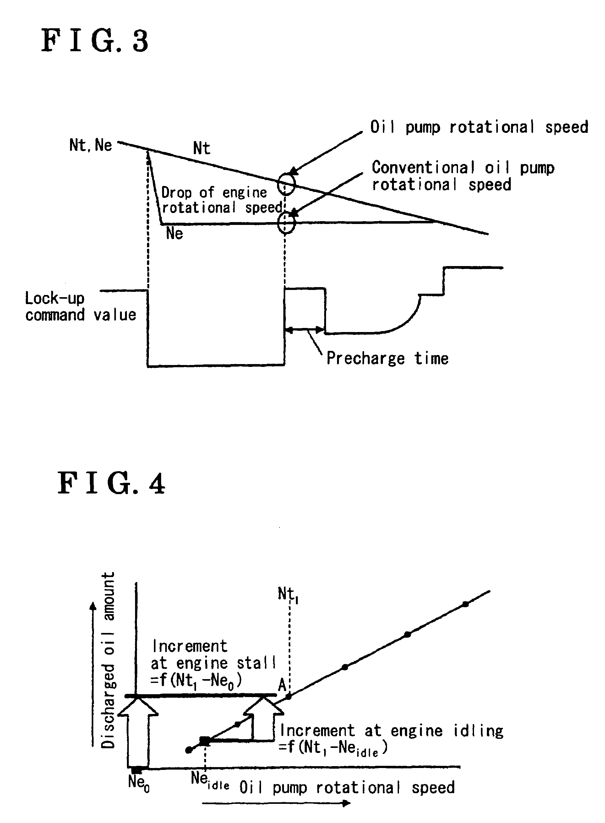
Therefore, while a lock-up clutch is being disengaged, or during a coast down state, an engine rotational speed (i.e., a rotational speed of a crankshaft) falls down about to a level of an idling rotational speed, by which the oil pump is disable to discharge an operating fluid at an adequate amount, and further it may become difficult to assure an enough level of an operating fluid pressure.
When an activation of an engine is discontinued, even by the oil pump apparatus disclosed above, it may be difficult to assure an oil pressure at a level which is required to control a shift operation or a lock-up clutch.
According to this oil pump apparatus, an entire structure may become complicated, and additional equipments, such as a motor pump, may be required, which may not be able to solve the above matters.

Method used


Image

  • Automatic transmission apparatus
  • Automatic transmission apparatus
  • Automatic transmission apparatus

Examples


Embodiment Construction

[0013]An embodiment of the present invention will be described hereinbelow in detail with reference to the accompanying drawings.

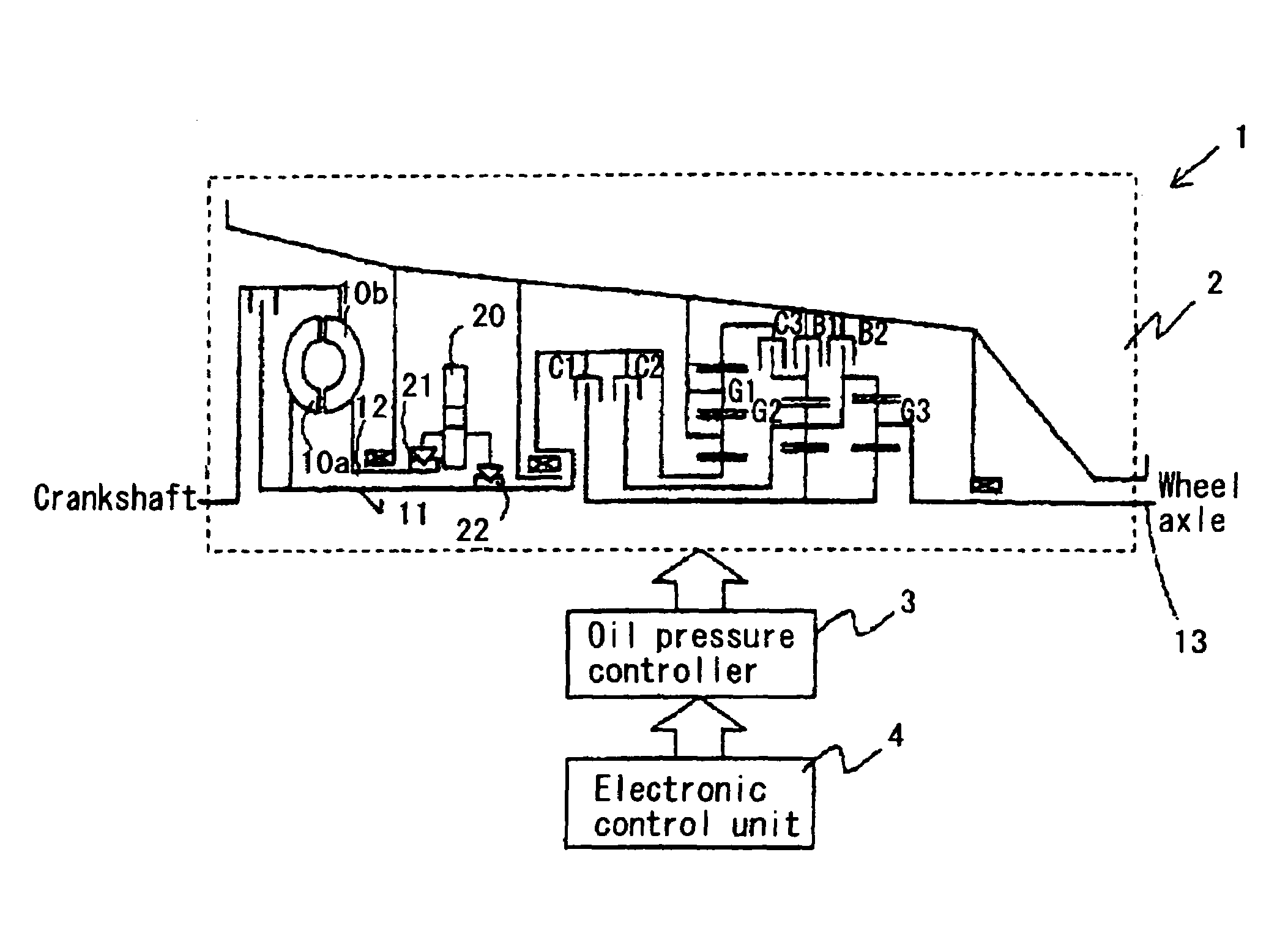
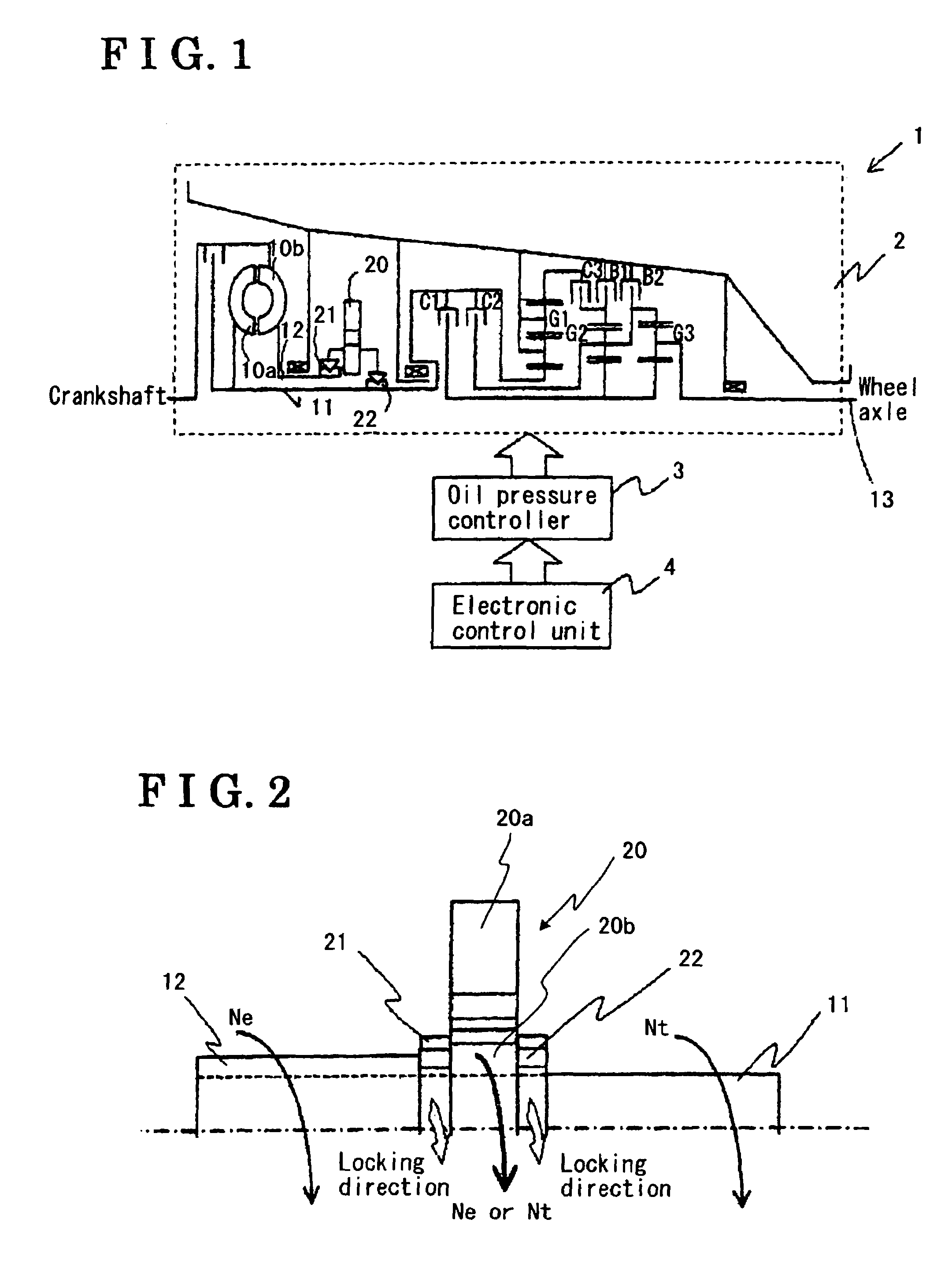
[0014]As is illustrated in FIG. 1, an automatic transmission apparatus 1 is provided with an automatic transmission 2, an oil pressure controller 3, and an electronic control unit 4 (i.e., a controlling means). The automatic transmission 2 incorporates, therein, an input shaft 11 connected to a turbine runner 10a (turbine) of a torque converter, an extension sleeve 12 connected to connected to a pump impeller 10b, an output shaft 13 connected to a wheel axle, and an A / T oil pump 20 connected to the input shaft 11 via a one-way clutch 22 (a second one-way clutch), and connected to the extension sleeve 12 via a one-way clutch 21 (a first one-way clutch). The automatic transmission 2 further incorporates, therein, a double-pinion planetary gear G1 connected to the input shaft 11, a second single-pinion planetary gear G2 and a third shingle-pinion planetary ge...


PUM


Abstract

An automatic transmission apparatus includes: a torque converter including a pump impeller connected to an engine and a turbine connected to an input shaft of an automatic transmission; an oil pump connected to the pump impeller and to the turbine; and a controlling means for selecting one of the engine and the turbine as a driving power source of the oil pump. The oil pump generates an oil pressure by rotation of the selected one of the engine and the turbine.

Description

CROSS REFERENCE TO RELATED APPLICATIONS[0001]This application is based on and claims priority under 35 U.S.C. §119 with respect to Japanese Patent Application 2004-280858, filed on Sep. 28, 2005, the entire content of which is incorporated herein by reference.FIELD OF THE INVENTION[0002]This invention generally relates to an automatic transmission apparatus. More specifically, this invention pertains to an automatic transmission apparatus having an oil pump by which an operating fluid is supplied to a plurality of clutches in an automatic transmission.BACKGROUND[0003]An oil pump, in other words a hydraulic pump, which supplies an operating fluid to an automatic transmission, is driven by an engine. Therefore, while a lock-up clutch is being disengaged, or during a coast down state, an engine rotational speed (i.e., a rotational speed of a crankshaft) falls down about to a level of an idling rotational speed, by which the oil pump is disable to discharge an operating fluid at an adeq...

Claims


Application Information

Patent Timeline
Patent Type & Authority Patents(United States)
IPC IPC(8): F16H61/58B60W10/02
CPCF16H61/0028F16H61/14Y10T477/635Y10T477/75Y10T477/79
Inventor TSUNEKAWA, KAZUTOSHI
Owner AISIN SEIKI KK
Learn More