Multiaxial connection for osteosynthesis

Inactive Publication Date: 2008-01-08
STRYKER EURO OPERATIONS HLDG LLC
View PDF17 Cites 228 Cited by
  • Summary
  • Abstract
  • Description
  • Claims
  • Application Information

AI Technical Summary

Benefits of technology

[0011]The first housing advantageously includes a U-shaped opening having an axis and two branches at a distance from and facing each other. The slot is located preferably perpendicular to the axis of the U-shaped opening. The branches of the U-shaped opening may include have a screwthread. The clamping means may include a locking member adapted to engage between the branches of the U-shaped opening. The clamping means or locking element may additionally include a flange adapted to fit around the branches of the U-shaped opening. Accordingly, when clamping the nut, the flange prevents spreading of the branches

Problems solved by technology

In the context of surgery on the vertebral column, and in particular when using a posterior approach route, the surgeon is often confronted with the problems of misalignment of the anchor members and interference between anchor members on two adjacent vertebrae.
This problem increases the operating time or prevents the surgeon from carrying out the desired procedure under the best possible conditions.
Th

Method used


Image

  • Multiaxial connection for osteosynthesis
  • Multiaxial connection for osteosynthesis
  • Multiaxial connection for osteosynthesis

Examples


first embodiment

[0023]the present invention is described with reference to FIGS. 1 to 6a.

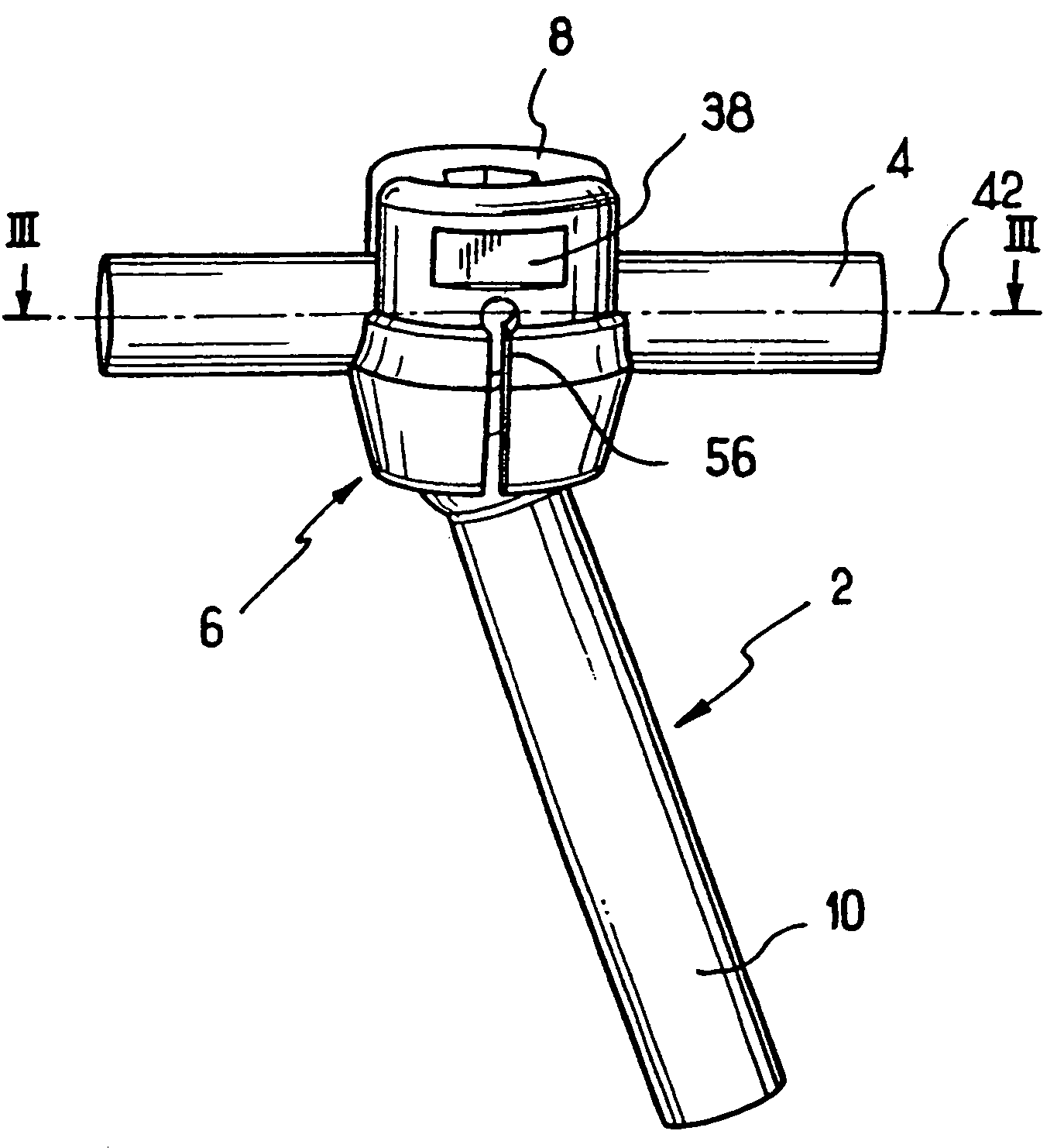
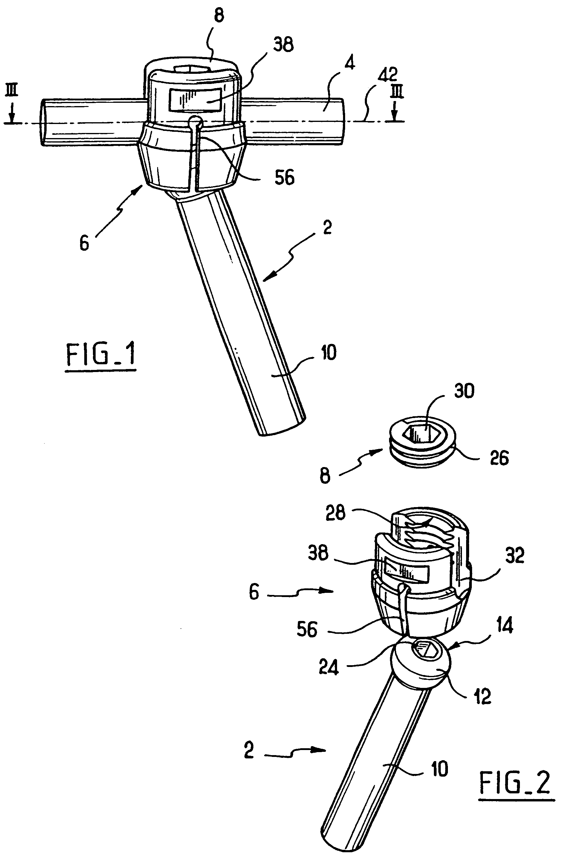
[0024]The osteosynthesis system includes at least two vertebral anchor members 2, connecting means 4, such as a rod, extending between the anchor member 2 and the other anchor member (not shown) of the osteosynthesis system, a connector 6 adapted to be fitted to the member 2, and clamping means, i.e. a locking member 8 adapted to cooperate with the connector 6.

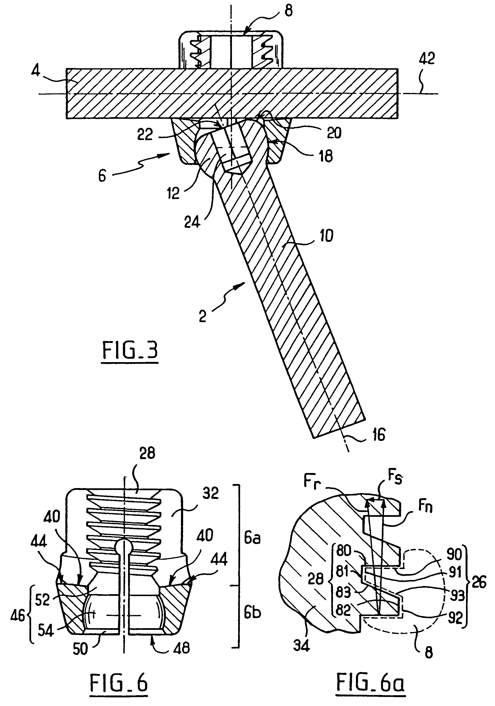
[0025]The vertebral anchor member 2, which in the preferred embodiment takes the form of a bone screw, may have a circular section cylindrical threaded body 10 carrying a bone thread (not shown). The preferred member 2 also may have a head 12 with a convex surface 14. The convex surface 14 has a surface of revolution whose axis coincides with the axis of the screw. The convex surface has a spherical lateral portion 18, a flat top portion 22, perpendicular to the axis of the screw, and a connecting fillet 20 between them, as shown in FIG. 3. The head 12 i...


PUM


Abstract

A multiaxial connection osteosynthesis system for the spine having a bone anchor, a connector and a connecting member. The bone anchor may be implanted into a vertebral body with a connector being attached to a head of the bone anchor. The connector includes a seat for receiving the connecting member. As the connecting member is locked into position it causes walls of the connector to inwardly deform and lock the head of the bone anchor relative to the connector.

Description

BACKGROUND OF THE INVENTION[0001]The present invention relates to a multiaxial connection osteosynthesis system, in particular for the spine.[0002]In the context of surgery on the vertebral column, and in particular when using a posterior approach route, the surgeon is often confronted with the problems of misalignment of the anchor members and interference between anchor members on two adjacent vertebrae. This problem increases the operating time or prevents the surgeon from carrying out the desired procedure under the best possible conditions. The cause of this problem is that the coupling member located between the member connecting the various vertebrae and the anchor member implanted in the vertebra is rigidly connected to the anchor member.[0003]Reference WO 97 / 02786 discloses a multiaxial connection between the members. The anchor member has a hemispherical head. The coupling member includes, in addition to means for receiving the member connecting the various vertebrae toget...

Claims


Application Information

Patent Timeline
IPC IPC(8): A61B17/56A61B17/58A61B17/70A61B17/86
CPCA61B17/7037A61B17/7032A61B17/8625A61B17/70
Inventor BACCELLI, CHRISTIANCONCHY, FREDERICGAUCHET, FABIENLE COUEDIC, REGISPASQUET, DENISSAINT MARTIN, PIERRE HENRITURNER-DOMERGUE, MICHELEVIENNEY, CECILE
Owner STRYKER EURO OPERATIONS HLDG LLC
Why Eureka
Try Eureka