Electric motor assisted takeoff device for an air vehicle

an air vehicle and assist device technology, applied in the direction of weapons, launch/towing gear, transportation and packaging, etc., can solve the problems of heat or acoustic signature, little or no visible,

Active Publication Date: 2008-01-15
PERATON INC
View PDF3 Cites 37 Cited by
  • Summary
  • Abstract
  • Description
  • Claims
  • Application Information

AI Technical Summary

Problems solved by technology

In addition, the takeoff assist device creates little or no detectable visible, heat or acoustic signature.

Method used


Image

  • Electric motor assisted takeoff device for an air vehicle
  • Electric motor assisted takeoff device for an air vehicle
  • Electric motor assisted takeoff device for an air vehicle

Examples


Embodiment Construction

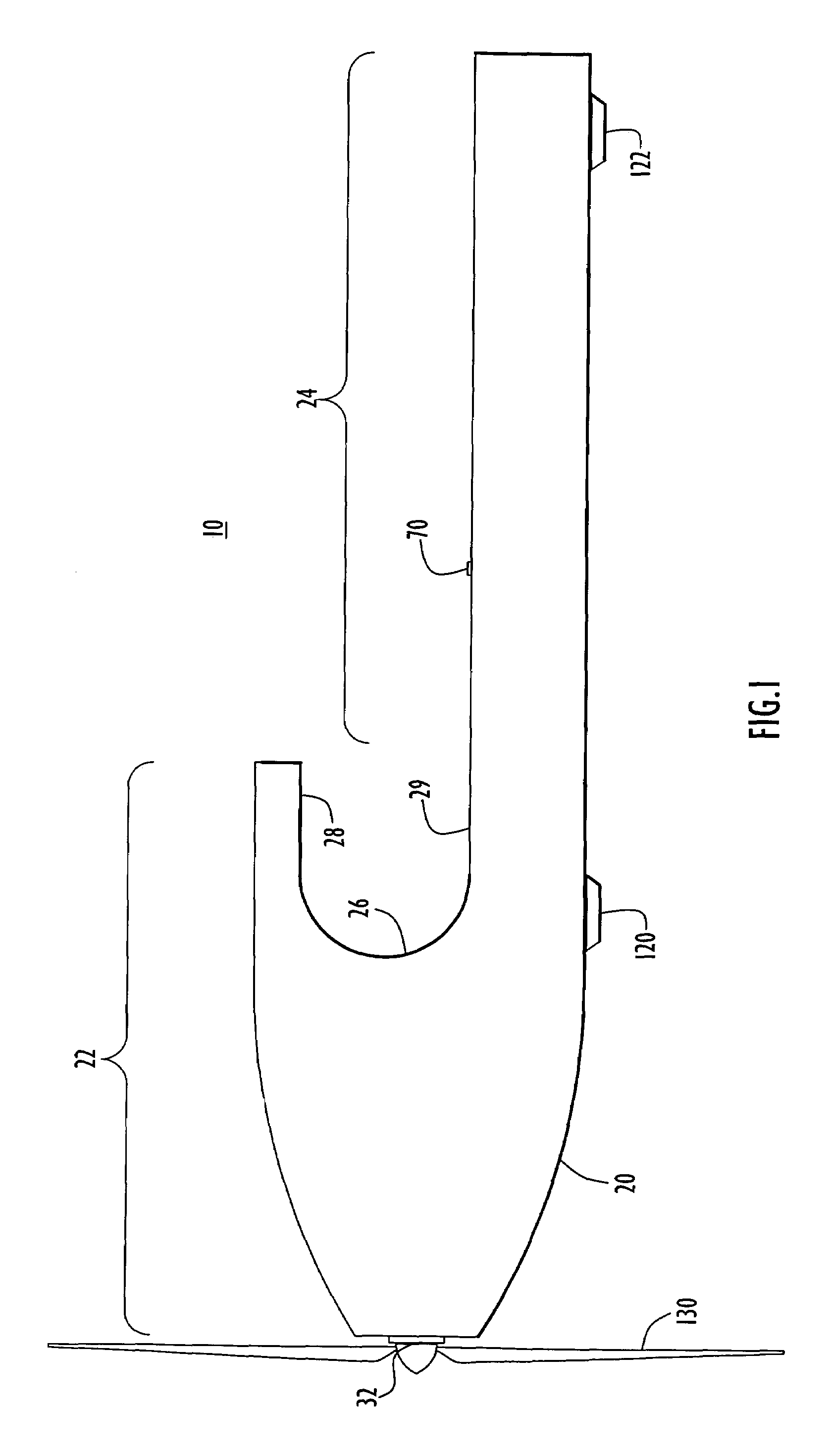
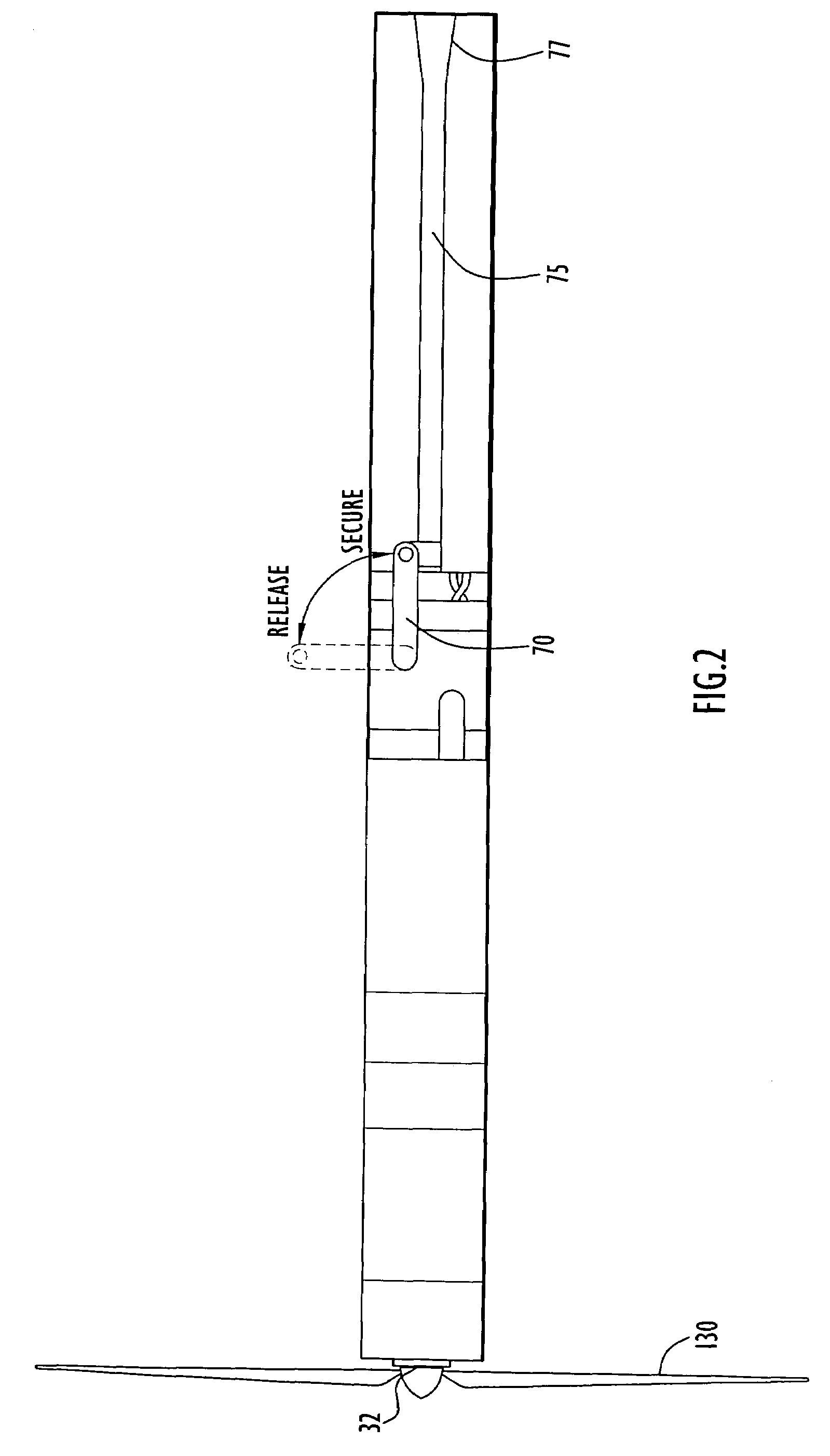
[0016]Referring first to FIGS. 1-5, the electric assist takeoff device shown generally at reference numeral 10 is described where FIG. 1 shows a side view of the exterior of the takeoff device 10, FIG. 2 shows a top view of the exterior of the takeoff device 10, FIG. 3 shows a front view of the takeoff device 10 and FIG. 4 shows a side cut-away view of the takeoff device 10 in which the components in the interior of the device 10 can best be seen.

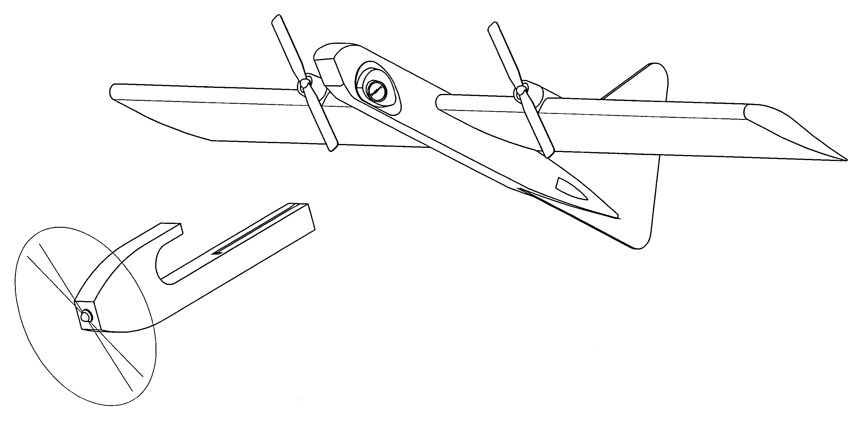
[0017]The takeoff device 10 comprises a body shell member 20 that contains an electric motor 30, a motor controller 40, a battery pack or sub-system 50 and a servo mechanism 60, a latch 70, a radio receiver 80 and a main controller 100. The body shell member 20 may, but need not be, of a shape that conforms to the shape of a host air vehicle so as to removeably fit over a nose portion of the host air vehicle. For example, body shell member 20 has a conical nose shape portion 22 to follow the contour of a nose portion of host air vehicle and...


PUM


Abstract

A takeoff assist device for an air vehicle, such as an unmanned air vehicle is provided. The device features an electric motor and is much less complex and lighter than takeoff assist devices heretofore known. A body member is shaped to fit to a portion of the air vehicle. The body member defines a housing in which the majority of the components are housed, including the electric motor, a motor controller, an electrical power source and a main controller. A propeller is attached to a shaft of the electric motor outside of the housing and rotates with a shaft of the electric motor. In addition, there is a latch mechanism that removeably attaches the body member to the host air vehicle for takeoff, and then is controlled to release from the air vehicle after it is airborne at a desired airspeed and altitude. The electric motor-driven takeoff assist device can launch an air vehicle with minimal auxiliary equipment and can be remotely controlled to launch from a site at which a takeoff ready vehicle can be left for extended periods of time.

Description

FIELD OF THE INVENTION[0001]The present invention relates to a takeoff assist device for a small aircraft, and more particularly to an electric motor driven takeoff assist device for unmanned air vehicles.BACKGROUND OF THE INVENTION[0002]Jet and rocket assisted takeoff modules have been in use for many years to provide reduced takeoff field size requirements for both manned and unmanned aircraft. These devices comprise one or more jet or rocket motor modules that attach to the aircraft to provide increased thrust and thus acceleration during takeoff. The device separates from the host aircraft once it is airborne to minimize the performance impact to the host aircraft.[0003]Jet and rocket assisted takeoff modules have serious limitations. Due to their pyrotechnic nature they are dangerous to use onboard ships at sea and / or for use on submarines. In addition, jet and rocket assisted takeoff modules produce a visible plume and create an easily detectable acoustic and heat signature th...

Claims


Application Information

Patent Timeline
Patent Type & Authority Patents(United States)
IPC IPC(8): B64F1/10
CPCB64C39/024F42B15/36B64C2201/021B64C2201/042B64C2201/082B64C2201/084B64C2201/104B64C2201/128B64C2201/146B64C2201/165B64U70/20B64U70/70B64U10/25B64U30/10B64U2101/60B64U50/19B64U50/13B64U2201/20B64U20/60B64U70/83B64U80/82B64U10/80B64U50/15
Inventor PAGE, GREGORY S.
Owner PERATON INC
Why Eureka
Try Eureka