Light receiving unit and image taking apparatus

a light receiving unit and image processing technology, applied in the field of two-plate type of light receiving units and image processing apparatuses, can solve problems such as camera shake, and achieve the effect of higher sensitivity

Inactive Publication Date: 2008-01-15
FUJIFILM CORP +1
View PDF8 Cites 12 Cited by
  • Summary
  • Abstract
  • Description
  • Claims
  • Application Information

AI Technical Summary

Benefits of technology

[0009]In view of the foregoing, it is an object of the present invention to provide an inexpensive light receiving unit having a high sensitivity characteristic that is hard to bring about a lack of brightness even if the high-speed shutter is used, and also to provide an image taking apparatus that suppresses an increment of the cost by means of arranging the inexpensive light receiving unit.

Problems solved by technology

This would involve a problem of the camera shake.

Method used


Image

  • Light receiving unit and image taking apparatus
  • Light receiving unit and image taking apparatus
  • Light receiving unit and image taking apparatus

Examples


Embodiment Construction

[0068]Embodiments of the present invention will be described with reference to the accompanying drawings.

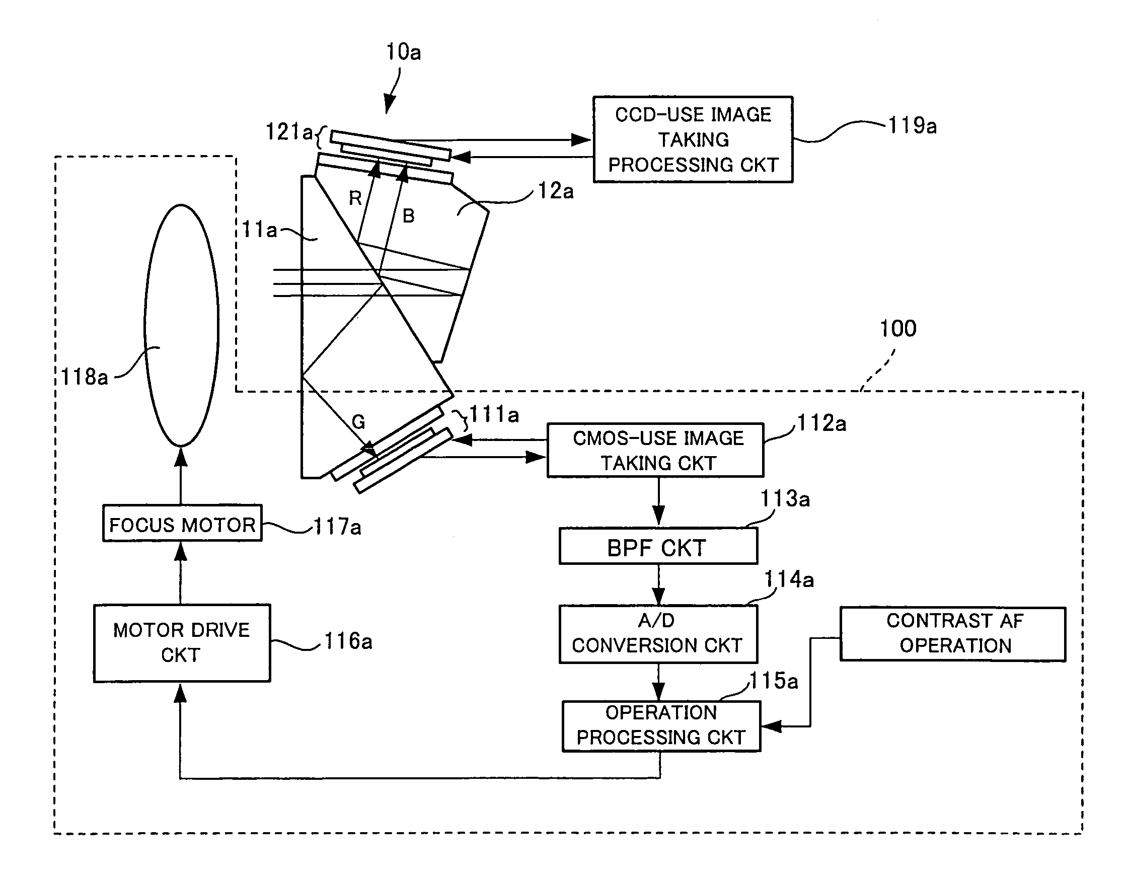
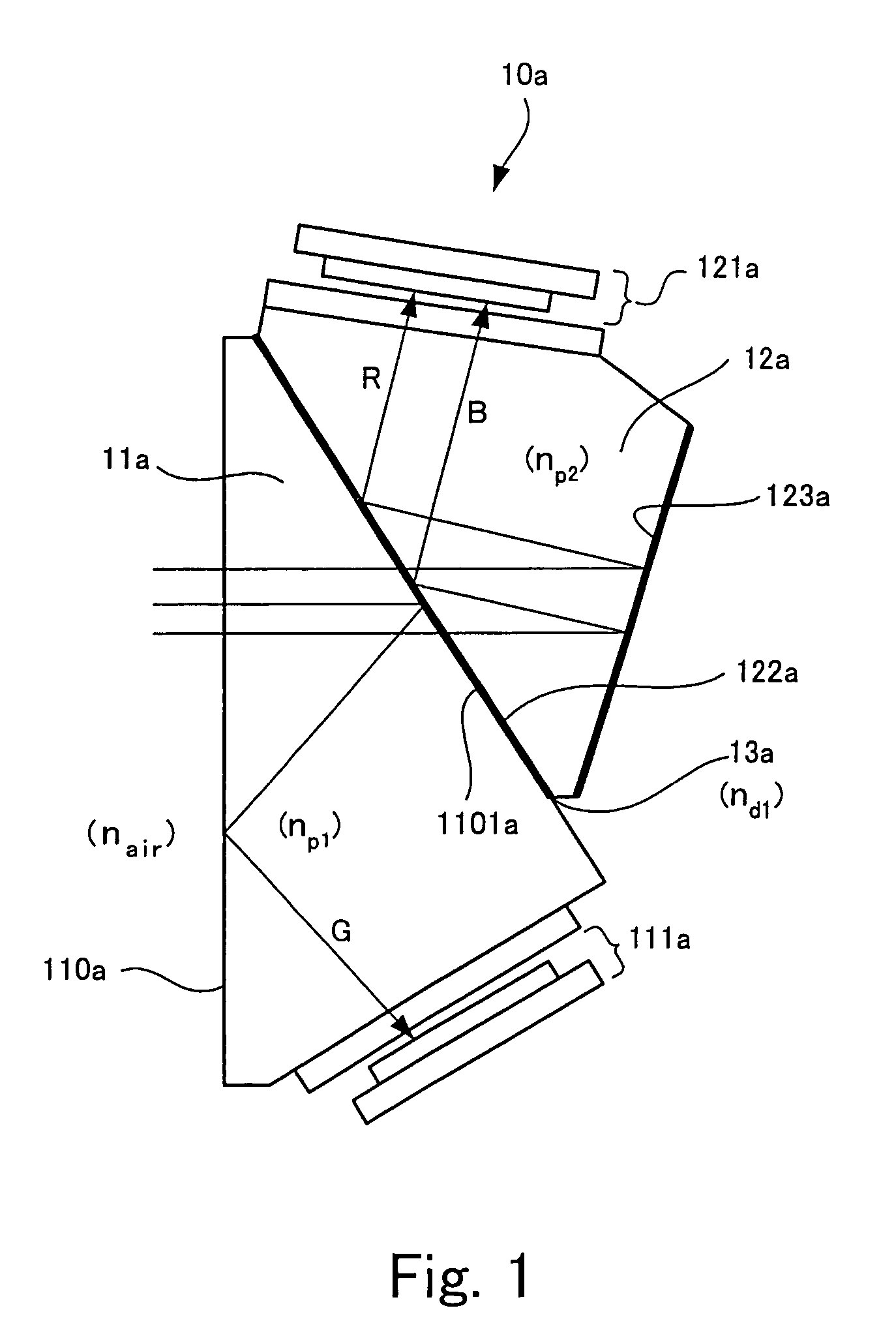
[0069]FIG. 1 is a view of a light receiving unit according to an embodiment of the present invention.

[0070]A light receiving unit 10a has two prisms 11a and 12a of polyhedron. One plane 1101a of the multiple planes of the prism 11a and one plane 122a of the multiple planes of the prism 12a are joined together. According to the present embodiment, in order to separate an incident light into a green wave-length band of light (hereinafter it is referred to as G-light), a red wave-length band of light (hereinafter it is referred to as R-light), and a blue wave-length band of light (hereinafter it is referred to as B-light), a dichroic mirror 13a, in which G-light is reflected and R-light and B-light are transmitted, is interposed between the prisms 11a and 12a.

[0071]Here, there will be explained functions of the dichroic mirror 13a and two prisms 11a and 12a.

[0072]The dichroic mirr...


PUM


Abstract

A first prism 11a and a second prism 12a are joined together on a face-to-face basis. A dichroic mirror 13a is interposed into the junction plane to reflect only G-light. A first imaging device 111a receives the reflected light (G-light) with high sensitivity. In this manner, there is constructed an inexpensive light receiving unit 10a having the same visual sensitivity characteristic as eyes of a person. The light receiving unit 10a is disposed in an image taking apparatus.

Description

BACKGROUND OF THE INVENTION[0001]1. Field of the Invention[0002]The present invention relates a two-plate type of light receiving unit and an image taking apparatus having the light receiving unit.[0003]2. Description of the Related Art[0004]In the event that upon receipt of light of the subject a color image according to the subject light is displayed, the color image is displayed on a display screen in such a way that the subject light is separated into R-color, G-color and B-color, that is, three primary colors of light, so that image signals associated with the respective colors are created, and then elements associated with R-color, G-color and B-color, which are arranged on the display screen on a two-dimensional basis, are driven by the image signals.[0005]To separate the subject light into R-color, G-color and B-color of three primary colors, according to a single-plate type of light receiving unit, R, G and B filters for color spectrum are arranged on a light receiving plan...

Claims


Application Information

Patent Timeline
Patent Type & Authority Patents(United States)
IPC IPC(8): G02B27/40
CPCH04N5/23212H04N9/045H04N9/097H04N23/673H04N23/84H04N23/16H04N25/134
Inventor SENBA, TAKEHIKO
Owner FUJIFILM CORP
Why Eureka
Try Eureka