Camera lifting apparatus and cargo handling operation aiding apparatus in industrial vehicle and industrial vehicle

a technology of lifting apparatus and cargo, which is applied in the direction of adaptive control, anti-theft devices, instruments, etc., can solve the problems of lowering working efficiency, limited camera attaching position, and difficulty in determining i

Inactive Publication Date: 2008-01-22
TOYOTA IND CORP
View PDF15 Cites 54 Cited by
  • Summary
  • Abstract
  • Description
  • Claims
  • Application Information

AI Technical Summary

Benefits of technology

[0014]It is a first object of the present invention to provide a camera lifting apparatus in an industrial vehicle, which can move a camera unit at an arbitrary height regardless of the heights of forks and can provide an adequate picked-up image of a cargo carrying work which is carried out at a high place.
[0015]It is a second object of the present invention to provide a camera lifting apparatus in an industrial vehicle, which can suppress the transmission of shocks of a camera unit hitting against a floor to an actuator.
[0016]It is a third object of the present invention to provide a cargo handling operation aiding apparatus in an industrial vehicle and an industrial vehicle, which can provide an adequate picked-up image according to a cargo carrying work by moving a camera to an image pickup position according to the cargo carrying work and can effectively support the cargo carrying work through the provided picked-up image.
[0017]It is a fourth object of the present invention to avoid the interference of a camera with surrounding objects at the time of a cargo carrying work.

Problems solved by technology

It is however extremely difficult to determine if the forks and a pallet or the like are horizontally positioned with the eyes by looking up at a high place from below, and even a skilled person needs time for this positioning.
In case of moving the forks gradually closer to a load or a rack by manipulating the lift lever, for example, the work should be carried out carefully, thus lowering the working efficiency.
Therefore, the camera attaching position was limited to a place, such as the distal end portion of the forks or the side surface of the forks, where miniaturization of the camera would be required.
The restriction of the camera attaching position might result in a case where the optimal aiding would be difficult.
Therefore, the camera might interfere with objects around at the time of a cargo carrying work.
Because the camera in the apparatus described in the aforementioned publication was secured relatively to the forks, however, it was not possible to change the position of the camera in accordance with a target that would differ in the contents of work.
However, the image pickup positions could not be switched by changing the positions of the cameras at arbitrary heights.
In case where plural cameras are arranged, extra cameras are needed and control of display on the screen of the display device becomes complicated.

Method used


Image

  • Camera lifting apparatus and cargo handling operation aiding apparatus in industrial vehicle and industrial vehicle
  • Camera lifting apparatus and cargo handling operation aiding apparatus in industrial vehicle and industrial vehicle
  • Camera lifting apparatus and cargo handling operation aiding apparatus in industrial vehicle and industrial vehicle

Examples


first embodiment

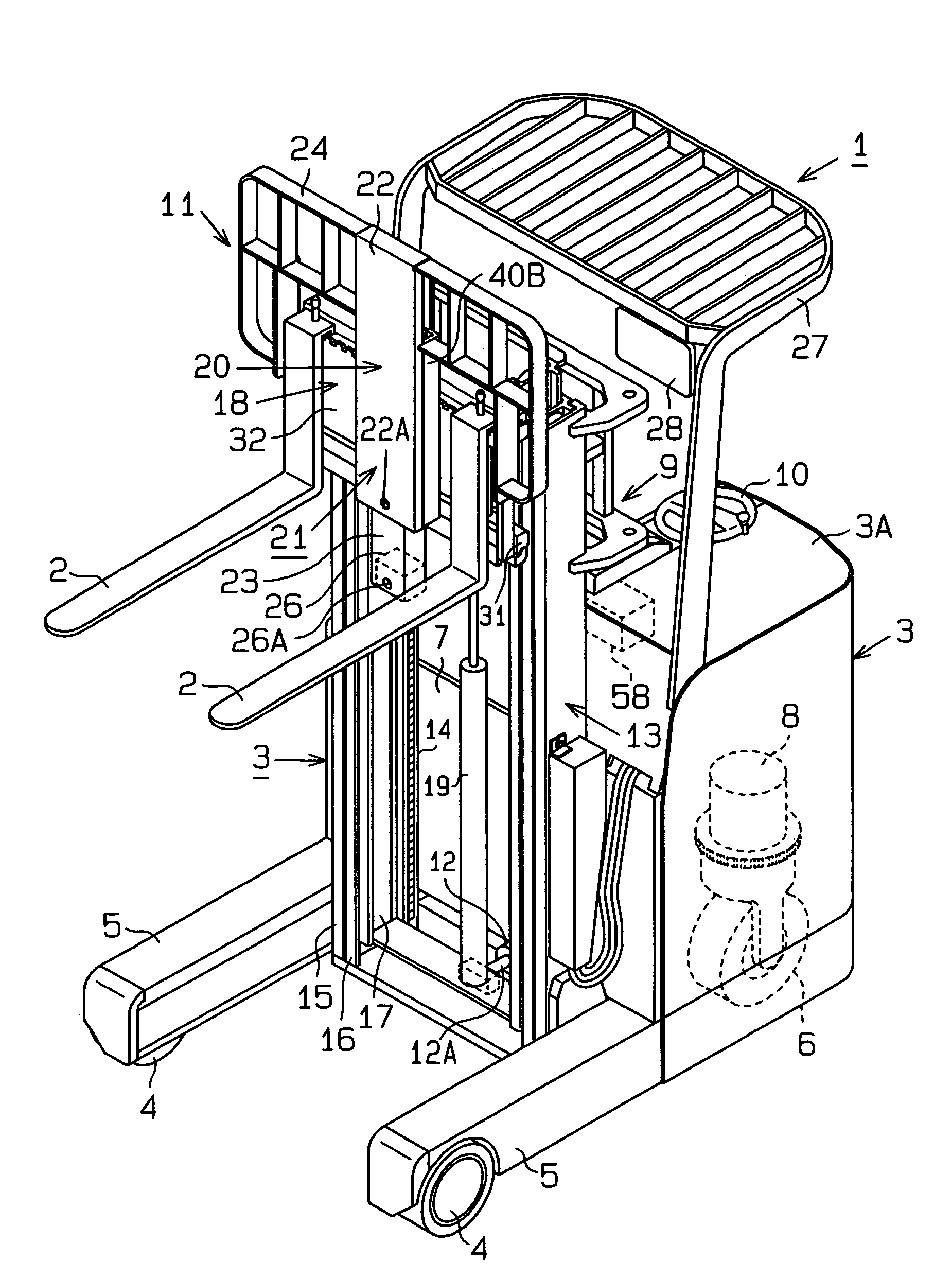
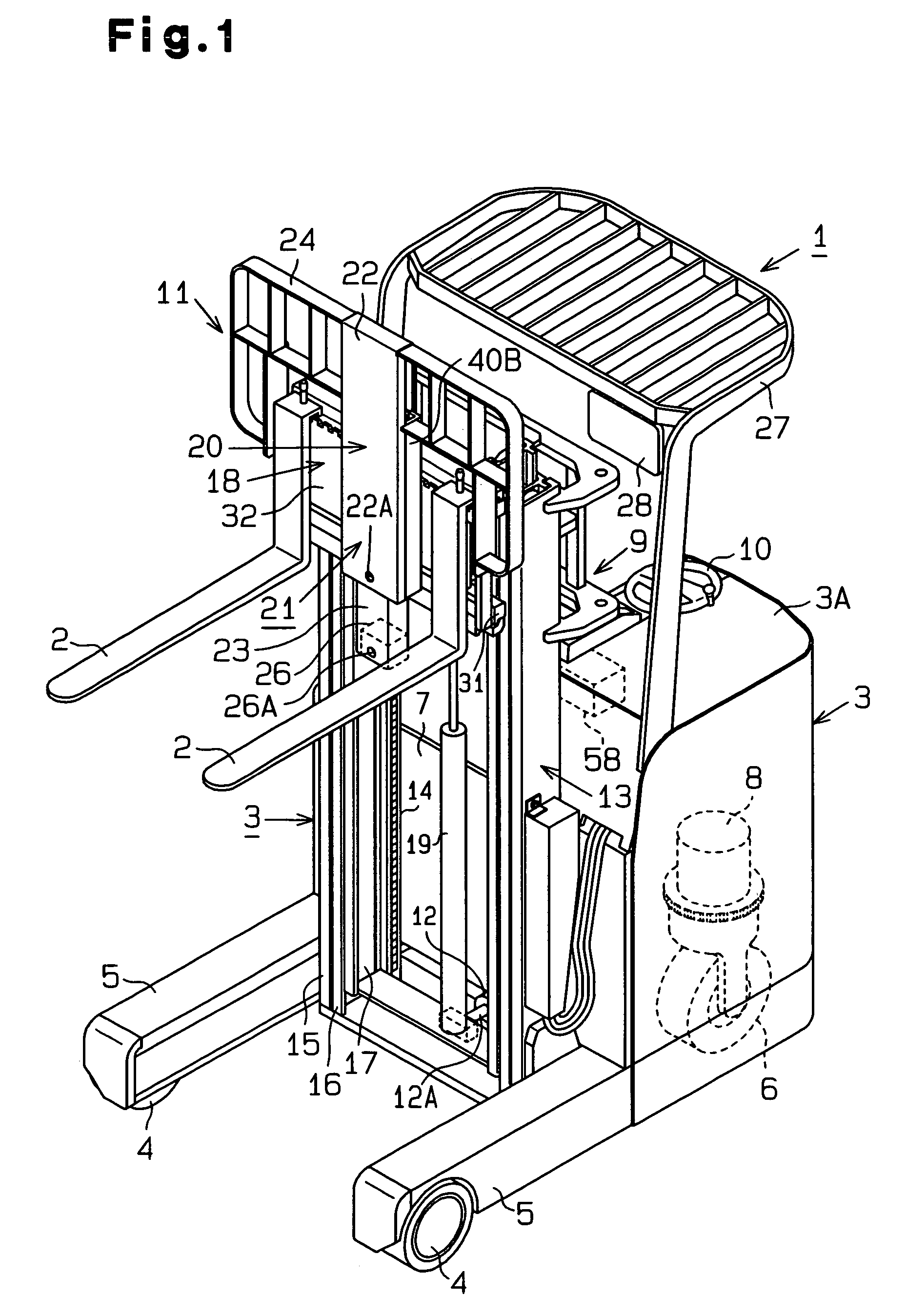
[0055]the present invention as embodied into a reach type forklift 1 as an industrial vehicle will be described below with reference to FIGS. 1 to 10.

[0056]As shown in FIG. 1, the forklift 1 is used to do a cargo carrying work in, for example, a factory. As a cargo carrying work, forks 2 as a cargo carrying apparatus are lifted up and down with respect to a rack provided upright in, for example, a factory to do load pickup and load deposition works. In a load pickup work, the forks 2 are inserted into a pallet 171 (see FIG. 14) stored, while carrying a load, in a rack. In this work, the forks 2 need to be positioned to the insertion holes of the pallet. In a load deposition work, a load (pallet) carried on the forks 2 are placed on a shelf surface 72A. In this work, the forks 2 should be positioned at a predetermined height above the shelf surface 72A (e.g., 10 to 20 cm above the shelf surface).

[0057]The forklift 1 is a three-wheel type with two front wheels and one rear wheel. The ...

second embodiment

[0122]Based on FIG. 11, the invention will be described mainly on those portions which differ from the embodiment in FIGS. 1 to 10.

[0123]An electric motor 96 and a belt 97 are used for the suspending mechanism of the camera unit 23 in the present embodiment. A drum 98 is coupled to the output shaft of the electric motor 96 as an actuator. The camera unit 23 is supported in a suspended fashion on the lower end of the belt 97 wound around the drum 98. As the electric motor 96 is driven, the drum 98 is rotated forward or in reverse, and the winding and feed-out of the belt 97 is selectively carried out in accordance with the rotation of the drum 98. In accordance with the winding and feed-out of the belt 97, the camera unit 23 is guided to the guide rails 40A and 40B for lifting control. Although FIG. 11 shows only the mechanism portion of the lifting apparatus of the camera 26, the sensors and control contents or the like are the same as those of the embodiment in FIGS. 1 to 10. In th...

third embodiment

[0124]Based on FIG. 12, the invention will be described mainly on those portions which differ from the embodiment in FIGS. 1 to 10.

[0125]A hydraulic cylinder 99 is used as an actuator in the present embodiment. The camera unit 23 is directly coupled to the distal end portion (lower end portion) of a piston rod 99A of the hydraulic cylinder 99. As the hydraulic cylinder 99 is driven, the piston rod 99A is protracted or retracted. In accordance with the protraction or retraction of the piston rod 99A, the camera unit 23 is lifted up or down. The hydraulic cylinder 99 is driven as the excitation / deexcitation control of an electromagnetic valve (not shown) provided in the hydraulic circuit is carried out by the controller 58, thus lifting the camera unit 23 up or down. Although FIG. 12 shows only the mechanism portion of the lifting apparatus of the camera 26, the sensors and control contents or the like are the same as those of the embodiment in FIGS. 1 to 10. In this embodiment too, t...


PUM


Abstract

A camera lifting apparatus is used in an industrial vehicle equipped with a cargo handling apparatus for lifting a cargo carrying carriage up and down along a mast provided on a vehicle body. The carriage has a cargo carrying apparatus. The camera lifting apparatus comprises a camera unit attached to the cargo carrying apparatus. The camera unit has a camera for picking up an image of a work area of the cargo carrying apparatus. A moving mechanism moves the camera unit relatively to the cargo carrying apparatus. An actuator drives the moving mechanism.

Description

BACKGROUND OF THE INVENTION[0001]The present invention relates to a camera lifting apparatus equipped with a camera unit for picking up the image of a work area of a cargo carrying apparatus, such as forks, at the time of doing a cargo carrying work in a high position and a cargo handling operation aiding apparatus in an industrial vehicle equipped with a carriage which is lifted up and down along a mast, such as, for example, a forklift.[0002]For example, the vehicle body of a forklift which is an industrial vehicle is equipped with a multi-level mast that lifts a carriage having an attachment, such as forks, up and down. At the time of performing load pickup or load deposition at a high place in a rack, a driver operates a lift lever to protract or retract the multi-level mast by hydraulic driving. Further, the driver moves the forks upward along the mast to position the forks to a predetermined position with respect to a shelf surface or a pallet on a rack (cargo handling lever o...

Claims


Application Information

Patent Timeline
Patent Type & Authority Patents(United States)
IPC IPC(8): B66F9/06B66F9/075B66F9/24
CPCB66F9/0755B66F9/24
Inventor KATAE, KENICHIICHIJO, HISASHIYAMANOUCHI, TORAHIKO
Owner TOYOTA IND CORP
Why Eureka
Try Eureka