
Suspension system for HVAC equipment

a suspension system and hvac equipment technology, applied in the direction of suspension devices, lighting and heating apparatus, heating types, etc., can solve the problems of difficult to achieve the proper pitch (or levelness) of the hvac unit, and the difficulty of achieving the proper pitch of the secondary pan, so as to achieve the effect of minimizing bumping or bending and being more reliabl

Inactive Publication Date: 2008-01-22
MAD METALS
View PDF15 Cites 30 Cited by
  • Summary
  • Abstract
  • Description
  • Claims
  • Application Information

AI Technical Summary

Benefits of technology

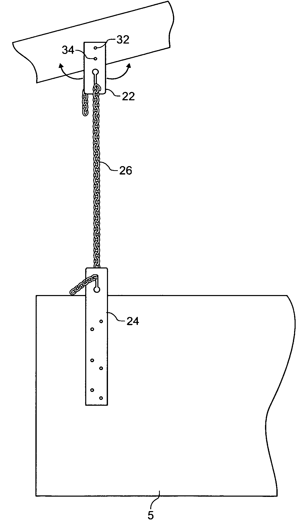
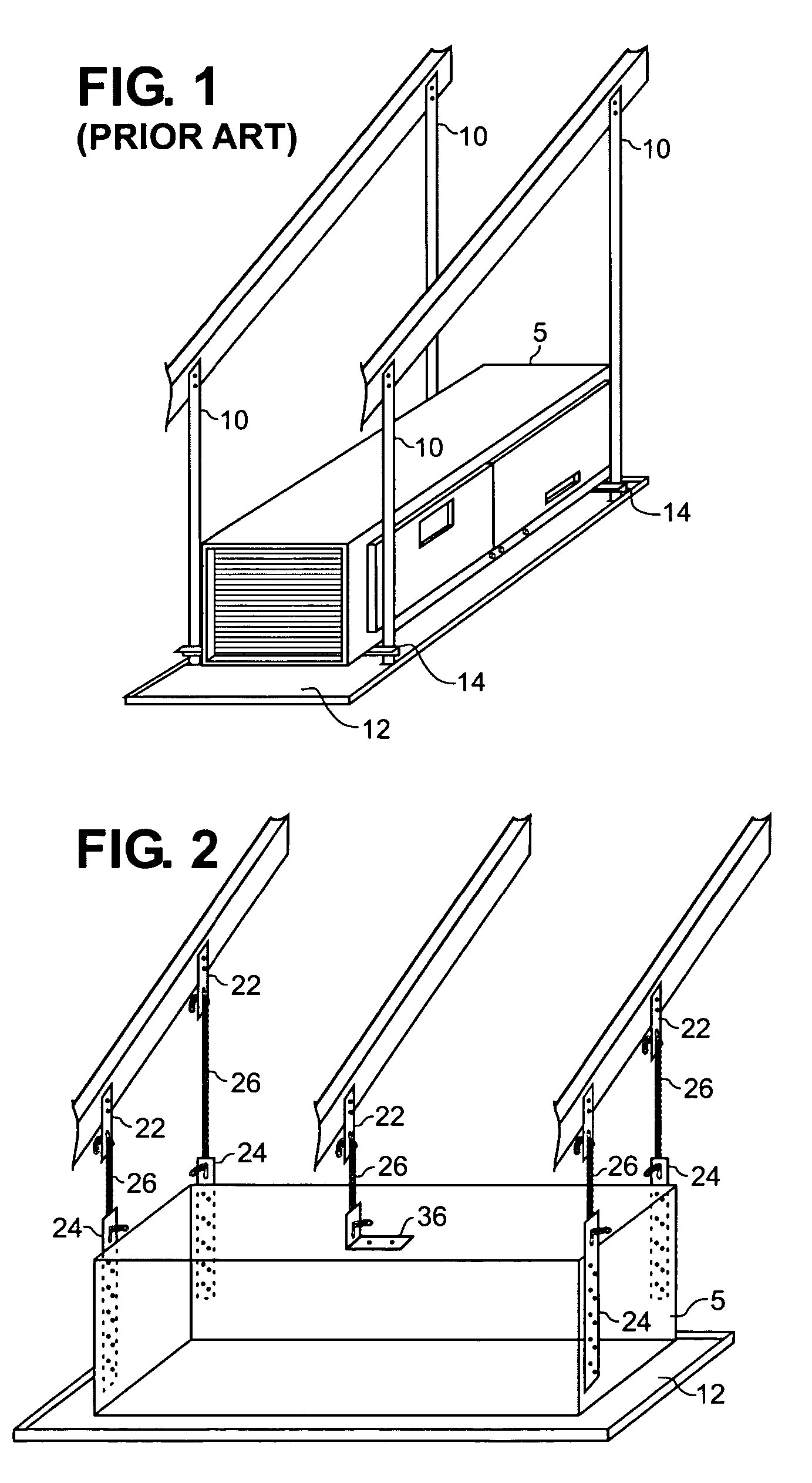
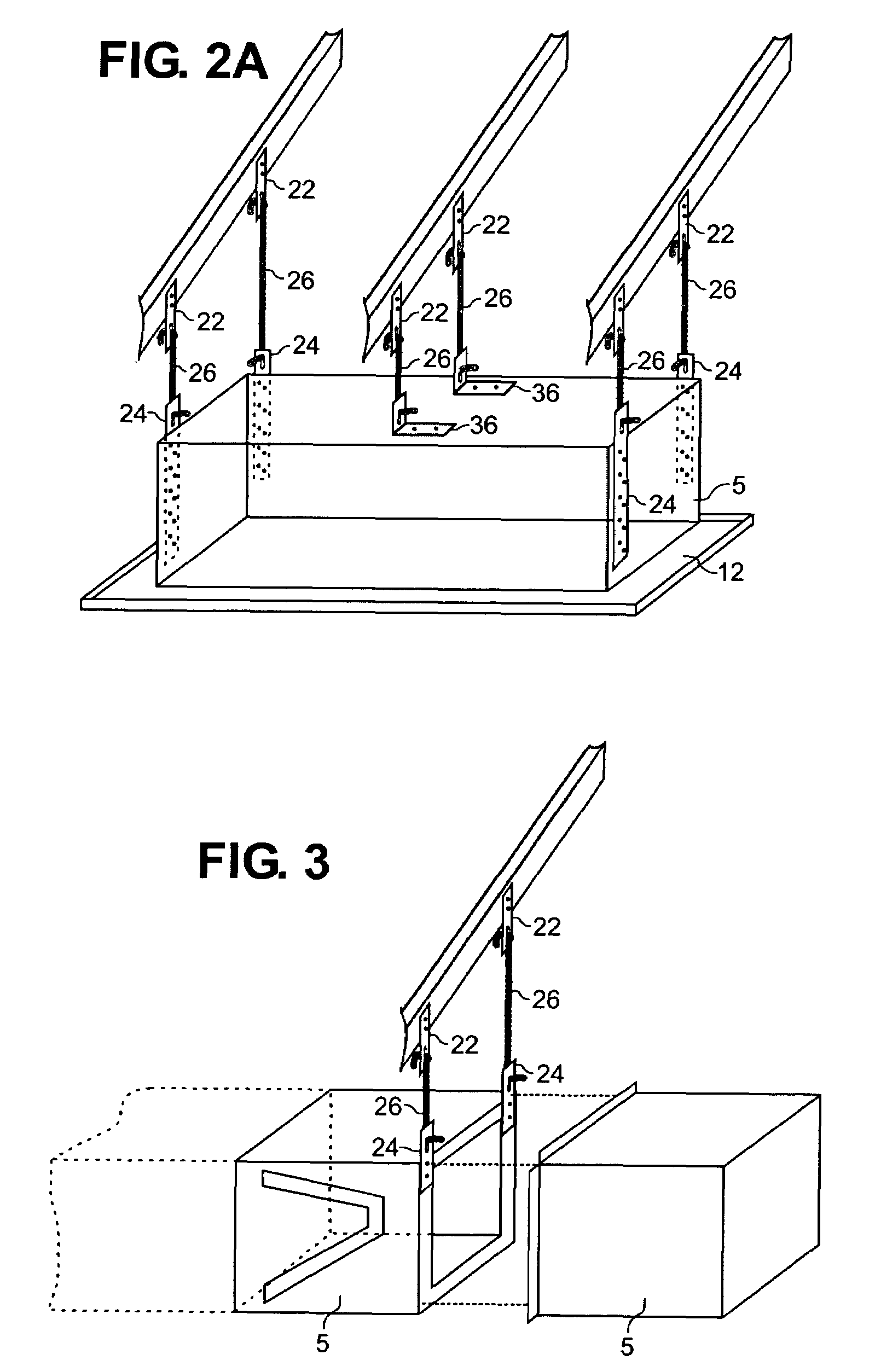
[0009]Generally, the present invention (referred to also as the “suspension system”) is incorporated in a system for suspending an HVAC unit 5 from one or more top support members through the use of one or more top lock plates 22 connected to the top support member, one or more bottom lock plates 24 connected to the HVAC unit 5, and one or more suspension chains 26 connected between the top lock plates 22 and the bottom lock plates 24. The suspension system provides a system for suspending HVAC equipment for residential and light commercial applications that is safer, quicker, cheaper, more reliable and more accurate than systems currently in use.
[0010]For example, the suspension system allows most residential and light commercial HVAC equipment to be installed by one person. The suspension system does not require the usage of heavy and relatively expensive angle iron. As described in more detail below, the suspension system can be adjusted at least twice during installation: (1) gross adjustments can be made by adjusting the lengths of suspension chain 26 through the top and bottom lock plates 22, 24 and (2) fine adjustments can be made by rotating the top lock plate 22 about the first fastening point 32 before fixing the second fastening point 34. The suspension system need not leave any sharp edges or sharp corners and edges that could injure the installers, other trades people or the owner. The suspension system permits the secondary pan 12 to be installed in close proximity to the HVAC unit 5 to minimize bumping or bending by other tradesmen and / or the owner. Similarly, the suspension system does not employ any angle iron 14, so no leakage bypasses the secondary pan 12 to drip on surfaces below.

Problems solved by technology

The prior art manner of installation requires the usage of heavy and relatively expensive angle iron 14.
The prior art manner of installation lacks adjustability, which makes it difficult to achieve the proper pitch (or levelness) of the HVAC unit 5.
The prior art manner of installation also makes it difficult to achieve the proper pitch for the secondary pan 12.

Method used


Image

  • Suspension system for HVAC equipment
  • Suspension system for HVAC equipment
  • Suspension system for HVAC equipment

Examples


Embodiment Construction

[0025]It is to be understood that the descriptions below are merely illustrative of the presently preferred embodiments of the invention and that no limitations are intended to the detail of construction or design herein shown other than as defined in the appended claims. In this specification, the term “HVAC unit” refers to a gas furnace and / or a heat pump air handler used in residential and light commercial applications or other similar HVAC equipment. Examples of an “HVAC unit” include those units manufactured by the CARRIER® Corporation under model numbers 58STA, 58DLA, 58CTA, 58CVA, 58STX, 58DLX, 58CTX, and 58CVX, those manufactured by GOODMAN® Manufacturing Company, L.P., those manufactured by American Standard, Inc. under the trademark TRANE® and those manufactured by YORK® International Corporation. Other air handlers, furnaces and related HVAC equipment could also be employed by the suspension system described herein. Similarly, while the description that follows is general...


PUM


Abstract

Generally, the present invention (referred to also as the “suspension system”) is incorporated in a system for suspending an HVAC unit from one or more wood truss members through the use of one or more top lock plates connected to the wood truss, one or more bottom lock plates connected to the HVAC unit, and one or more suspension chains connected between the top lock plates and the bottom lock plates. The suspension system provides a system for suspending HVAC equipment in residential and light commercial applications that is safer, quicker, cheaper, more reliable and more accurate than systems currently in use.

Description

CROSS-REFERENCE TO RELATED APPLICATIONS[0001]The present application claims the benefit of U.S. Provisional Application No. 60 / 548,491 filed Feb. 27, 2004, which is entirely incorporated herein by reference.BACKGROUND OF THE INVENTION[0002]1. Field of the Invention[0003]The present invention relates generally to installation of residential and light commercial HVAC equipment, and more particularly to suspension systems for air handlers, gas furnaces, and related HVAC equipment in attics and crawlspaces.[0004]2. Discussion of the Related Art[0005]Currently, residential and light commercial HVAC equipment, including air handlers and gas furnaces, are typically installed in attics and crawlspaces in the manner illustrated in FIG. 1 (referred to herein as the “prior art manner of installation”). FIG. 1 shows 22-gauge sheet metal strapping 10, nailed to overhead wood trusses at the top and connected to a secondary pan 12 at the bottom. Near the bottom, a length of angle iron 14 is connec...

Claims


Application Information

Patent Timeline
Patent Type & Authority Patents(United States)
IPC IPC(8): A47H1/00A47H1/10E04D1/36F24F13/32
CPCF24F13/32
Inventor BERLYN, DANIEL ECOLE, WARD D.HALL, BRADLEY KEVINWILKIE, STEVEN JOSEPHCOLE, FRANK EDWARD
Owner MAD METALS
Learn More