
Optical down-converter using universal frequency translation technology

a technology of universal frequency translation and optical signal, applied in the field of conversion of optical signals, can solve the problems of increasing overall cost, high parts count, and high cost of conventional optical signal conversion circuitry

Inactive Publication Date: 2008-01-22
PARKER VISION INC
View PDF726 Cites 72 Cited by
  • Summary
  • Abstract
  • Description
  • Claims
  • Application Information

AI Technical Summary

Benefits of technology

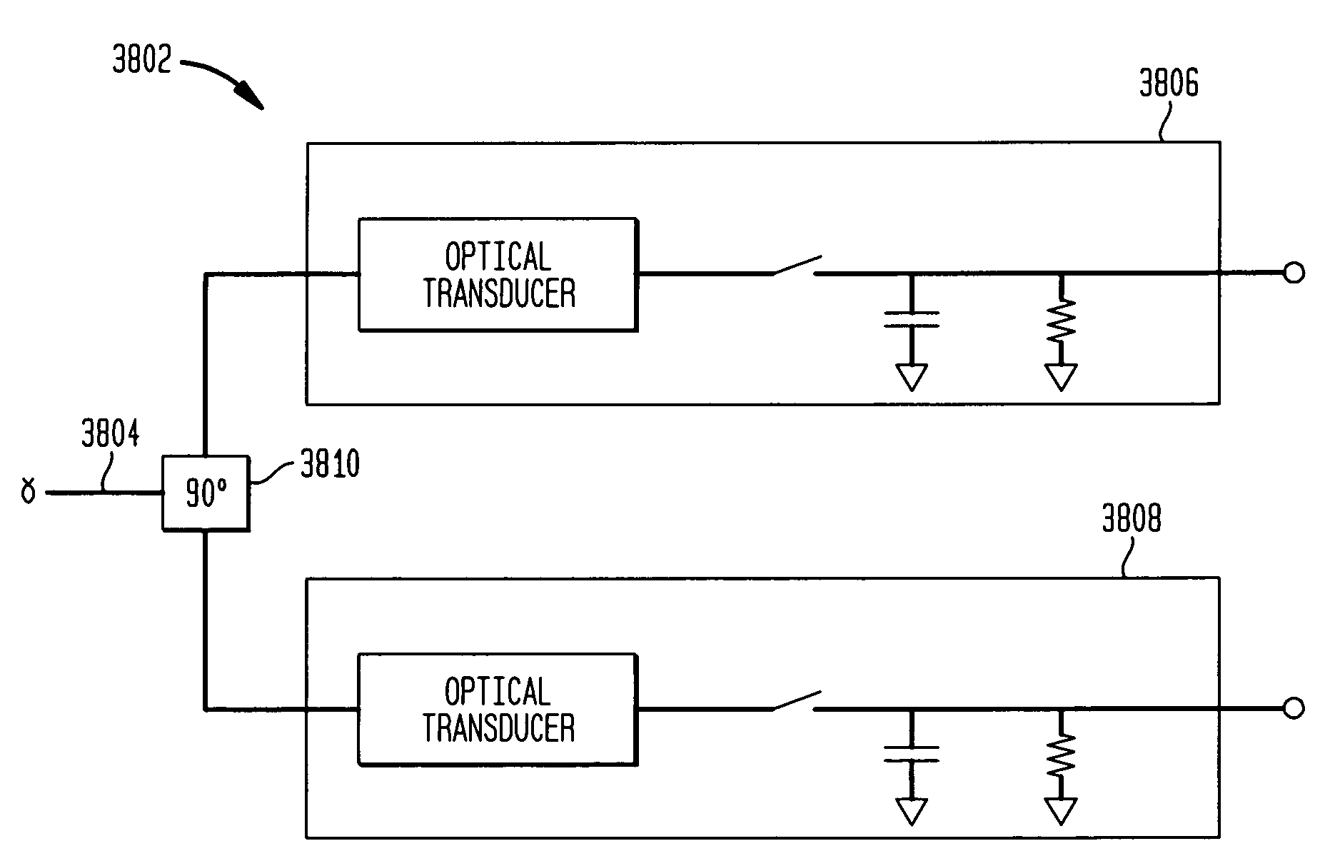
"The present invention is about methods and systems for converting optical signals to electrical signals. The optical signal is first converted to electrical charge, and then this charge is periodically transferred to a storage device, resulting in the formation of electrical signals. These signals can include both demodulated baseband information and modulated signals like RF signals. The invention can also be used to convert I and Q optical signals. The technical effects of this invention include improved optical signal-to-electrical signal conversion and improved performance of optical devices."

Problems solved by technology

Conventional methods and systems for converting optical signals to electrical suffer from the disadvantage of being relatively expensive in terms of cost and power consumption.
Conventional optical signal conversion circuitry is complex and has a large number of circuit parts.
This complexity and high parts count increases overall cost.
Additionally, higher part counts result in higher power consumption, which is undesirable, particularly in battery powered repeater units.

Method used


Image

  • Optical down-converter using universal frequency translation technology
  • Optical down-converter using universal frequency translation technology
  • Optical down-converter using universal frequency translation technology

Examples


example application embodiments

7. EXAMPLE APPLICATION EMBODIMENTS OF THE INVENTION

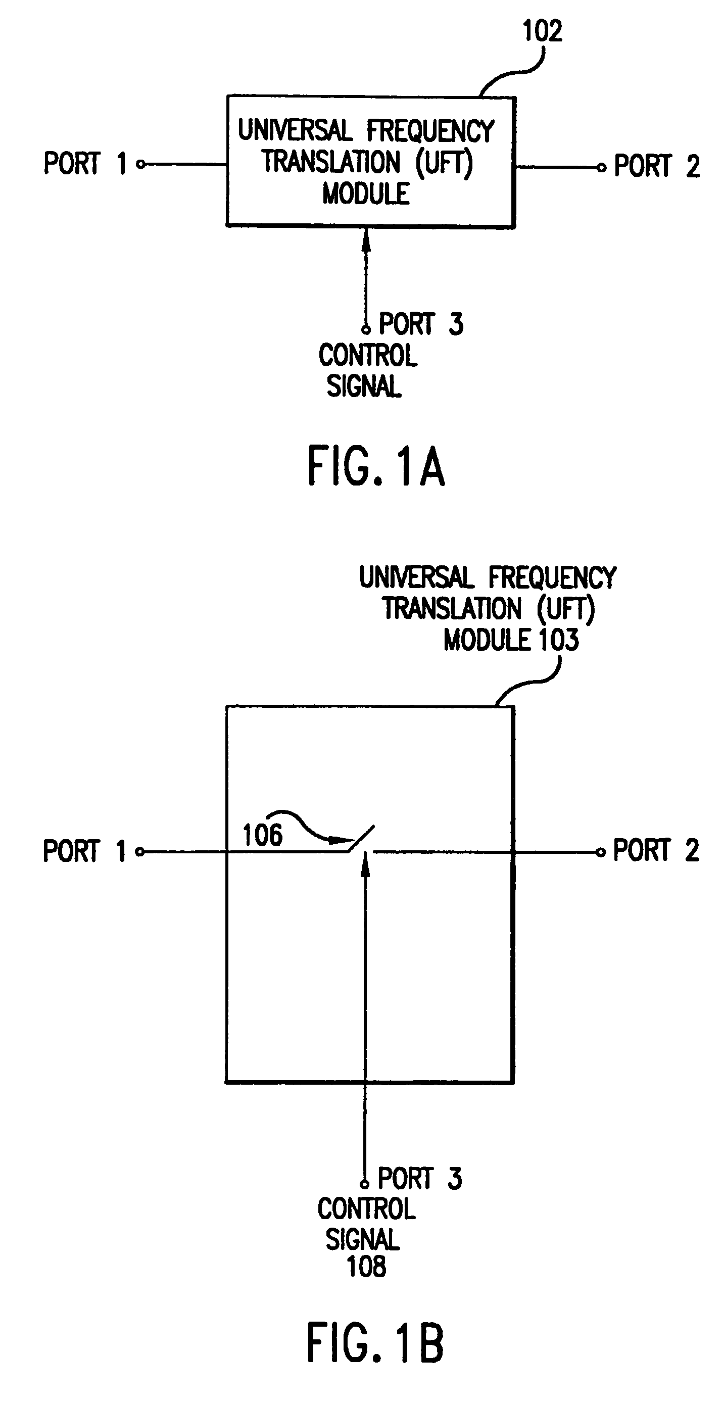
[0351]As noted above, the UFT module of the present invention is a very powerful and flexible device. Its flexibility is illustrated, in part, by the wide range of applications in which it can be used. Its power is illustrated, in part, by the usefulness and performance of such applications.

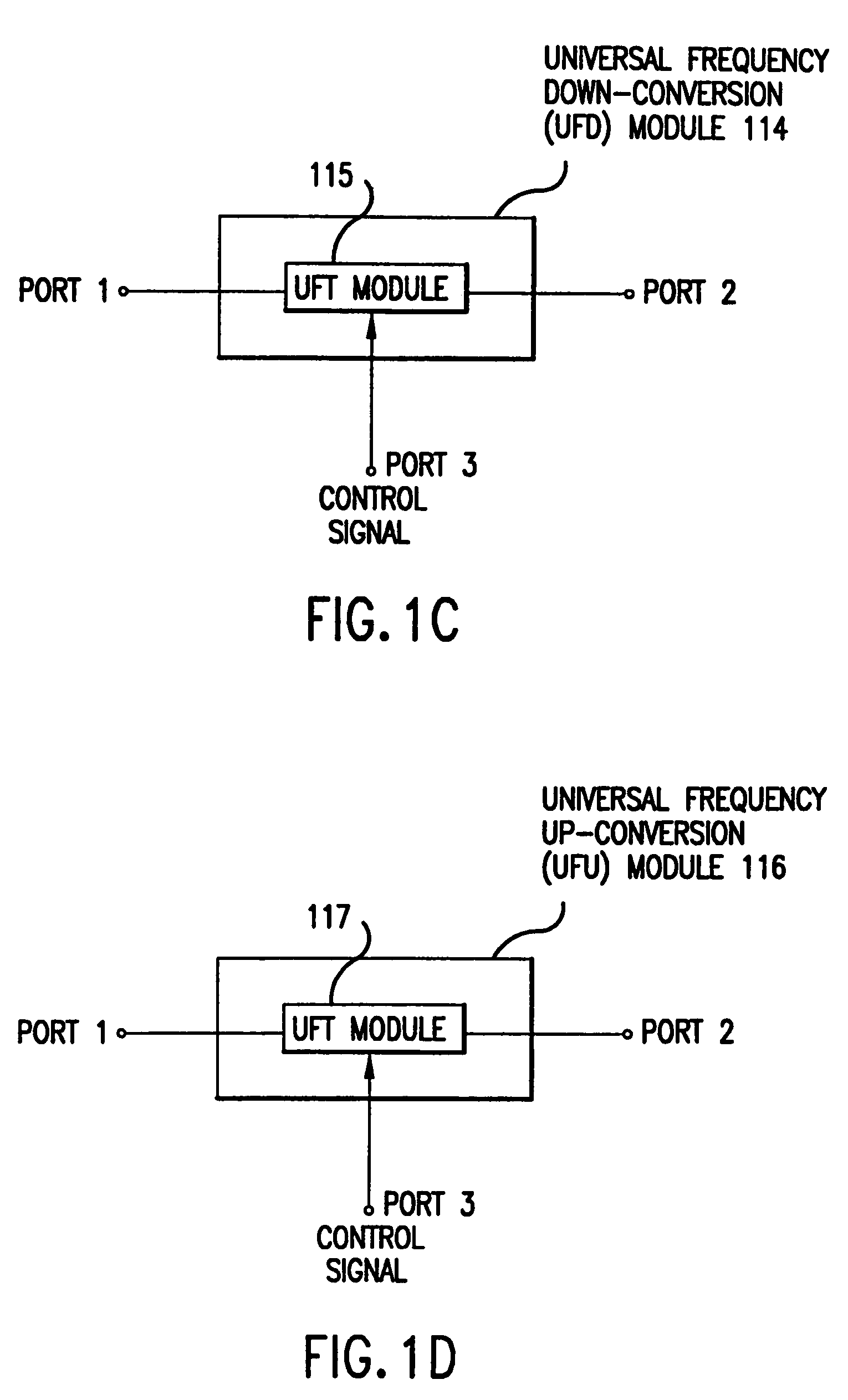
[0352]Example applications of the UFT module were described above. In particular, frequency down-conversion, frequency up-conversion, enhanced signal reception, and unified down-conversion and filtering applications of the UFT module were summarized above, and are further described below. These applications of the UFT module are discussed herein for illustrative purposes. The invention is not limited to these example applications. Additional applications of the UFT module will be apparent to persons skilled in the relevant art(s), based on the teachings contained herein.

[0353]For example, the present invention can be used in applications that inv...


PUM


Abstract

A method and system for converting an optical signal to electrical information signals, including demodulated baseband information signals and modulated baseband signals at multiple harmonics. In an embodiment, the optical information signal is amplitude modulated with information. The method converts an optical signal to electrical charge, accumulates the electrical charge, and periodically transfers the accumulated electrical charge to a storage device, whereby the periodically transferred electrical charge forms the electrical signals. An exemplary system includes an optical transducer and a universal frequency translator coupled to an output of the optical transducer. The optical transducer receives an optical signal and converts the optical signal to electrical charge. The universal frequency translator periodically transfers energy from the electrical charge and forms the electrical signals from the transferred energy. In an embodiment, the present invention converts an I and Q optical signal to electrical signals. In an embodiment, the present invention converts an optical signal to an RF electrical signal using relatively few components, while preserving information content.

Description

[0001]This application is a continuation-in-part of the following U.S. applications:[0002]Ser. No. 09 / 376,359, filed Aug. 18, 1999, titled “Method and System for Down-Converting Electromagnetic Signals by Sampling and Integrating Over Apertures Method and System for Down-Converting an Electromagnetic Signal”, issued as U.S. Pat. No. 6,266,518 B1;[0003]Ser. No. 09 / 521,879, filed Mar. 9, 2000 now abandoned, titled “Matched Filter Characterization and Implementation of Universal Frequency Translation Method and Apparatus”;[0004]Ser. No. 09 / 550,644, filed Apr. 14, 2000, titled, “Method and System for Down-converting Electromagnetic Signal, Transforms for the Same, and Aperture Relationships,”; and[0005]Ser. No. 09 / 176,154, filed Oct. 21, 1998, titled, “Method and System for Frequency Up-Conversion”, now issued as U.S. Pat. No. 6,091,940.CROSS-REFERENCE TO OTHER APPLICATIONS[0006]The following applications of common assignee are related to the present application, and are herein incorpor...

Claims


Application Information

Patent Timeline
Patent Type & Authority Patents(United States)
IPC IPC(8): H04B10/06H04B17/40
CPCH03D7/00
Inventor SMITH, FRANCIS J.BULTMAN, MICHAEL J.COOK, ROBERT W.LOOKE, RICHARD C.MOSES, JR., CHARLEY D.RAWLINS, GREGORY S.RAWLINS, MICHAEL W.SHORT, ROBERT T.SORRELLS, DAVID F.STONEKING, DANNY E.
Owner PARKER VISION INC
Learn More