Keyboard apparatus

a keyboard and keyboard technology, applied in the field of keyboard apparatus, can solve the problems of insufficient bending rigidity and twisting rigidity relative to the scale direction, inability to achieve sufficient rigidity, inability to achieve sufficient twisting rigidity, etc., to achieve simple construction, increase rigidity, and not increase the weight of the keyboard apparatus

Active Publication Date: 2008-02-05
YAMAHA CORP
View PDF8 Cites 17 Cited by
  • Summary
  • Abstract
  • Description
  • Claims
  • Application Information

AI Technical Summary

Benefits of technology

[0007]In view of the foregoing, it is an object of the present invention to provide an improved keyboard apparatus which has an increased rigidity through a combination of a frame and body section (casing) even with a simple construction that does not increase the weight of the keyboard apparatus.
[0009]According to the present invention, the frame, on which the plurality of keys are operably mounted, has the continuous surface defining the channel-shaped concave section extending in the key-arranged (or note scale) direction, and the body section, in which the frame is mounted, has the supporting surface that contacts the opposite sides of the opening of the channel-shaped concave section of the frame. The opposite sides of the opening of the channel-shaped concave section of the frame are fixed to the supporting surface of the body section. Thus, a closed-section structure is formed or defined by the channel-shaped concave section of the frame and the supporting surface of the body section, which constitutes a “semi-monocoque” structure extending in the key-arranged direction. Such a structure can enhance bending rigidity and twisting rigidity relative to the note scale direction (key-arranged direction).

Problems solved by technology

Thus, in this case too, sufficient bending rigidity and twisting rigidity relative to the scale direction is not achievable.
In this case, the space defined by the frame 2 and casing 3 has a closed sectional shape, but, because the closed space has a considerably great sectional area, the frame 2 and casing 3 can easily flex so that sufficient rigidity is hardly achievable.
Further, although the concavo-convex structure, extending in the note scale (key-arrange) direction, can function to enhance the bending rigidity relative to the note scale (key-arrange) direction, sufficient twisting rigidity is hardly achievable because the end surfaces of the concavo-convex structure are not positively fixed.
It is conceivable to reinforce the underside or the like with an external member 6 to thereby secure sufficient rigidity of the entire keyboard apparatus as illustrated in FIG. 10; however, such an approach can not said to be advisable because the provision of the reinforcing member would result in various inconveniences, such as an increased cost and increased weight.

Method used


Image

  • Keyboard apparatus
  • Keyboard apparatus
  • Keyboard apparatus

Examples


first embodiment

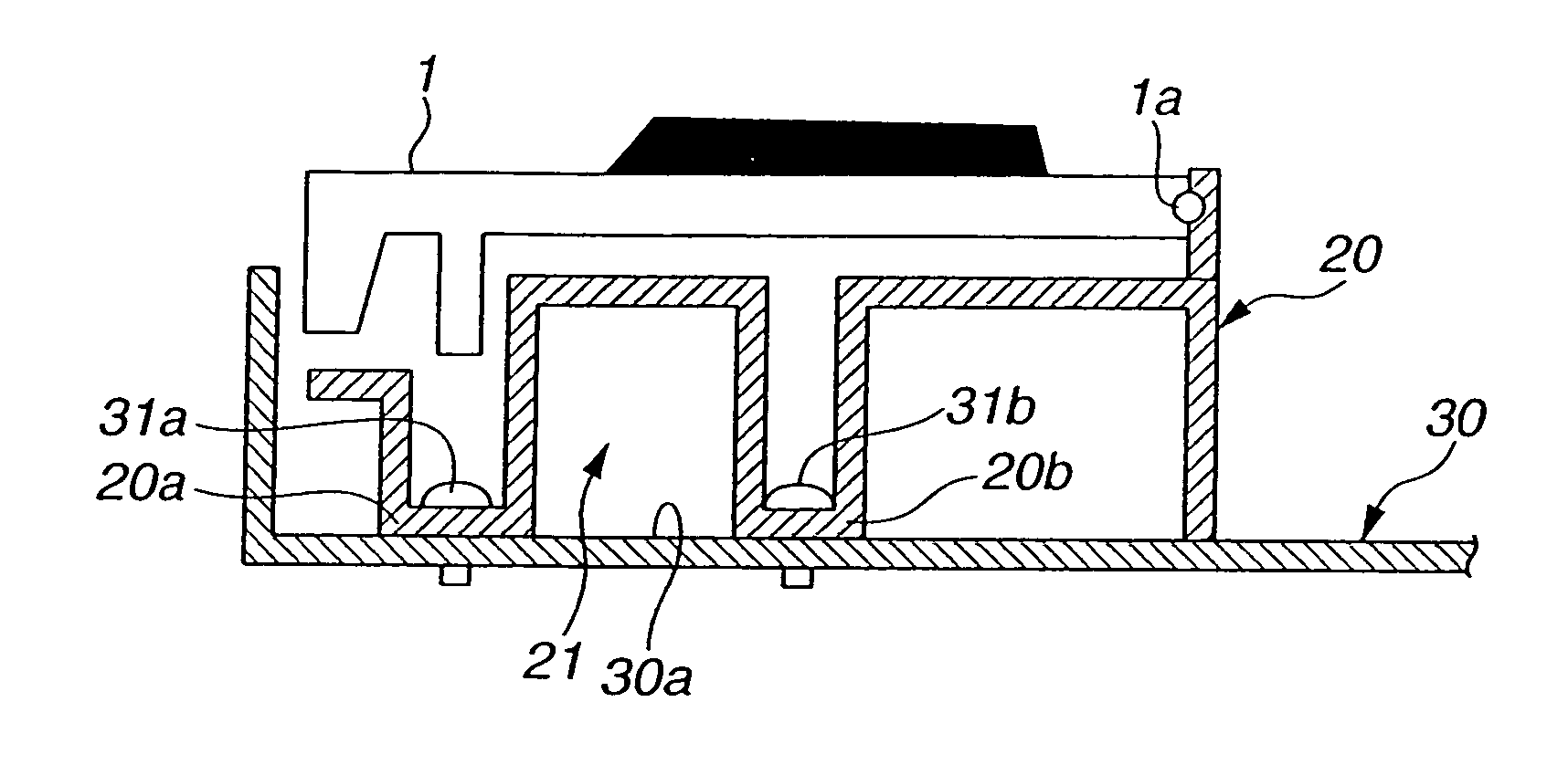
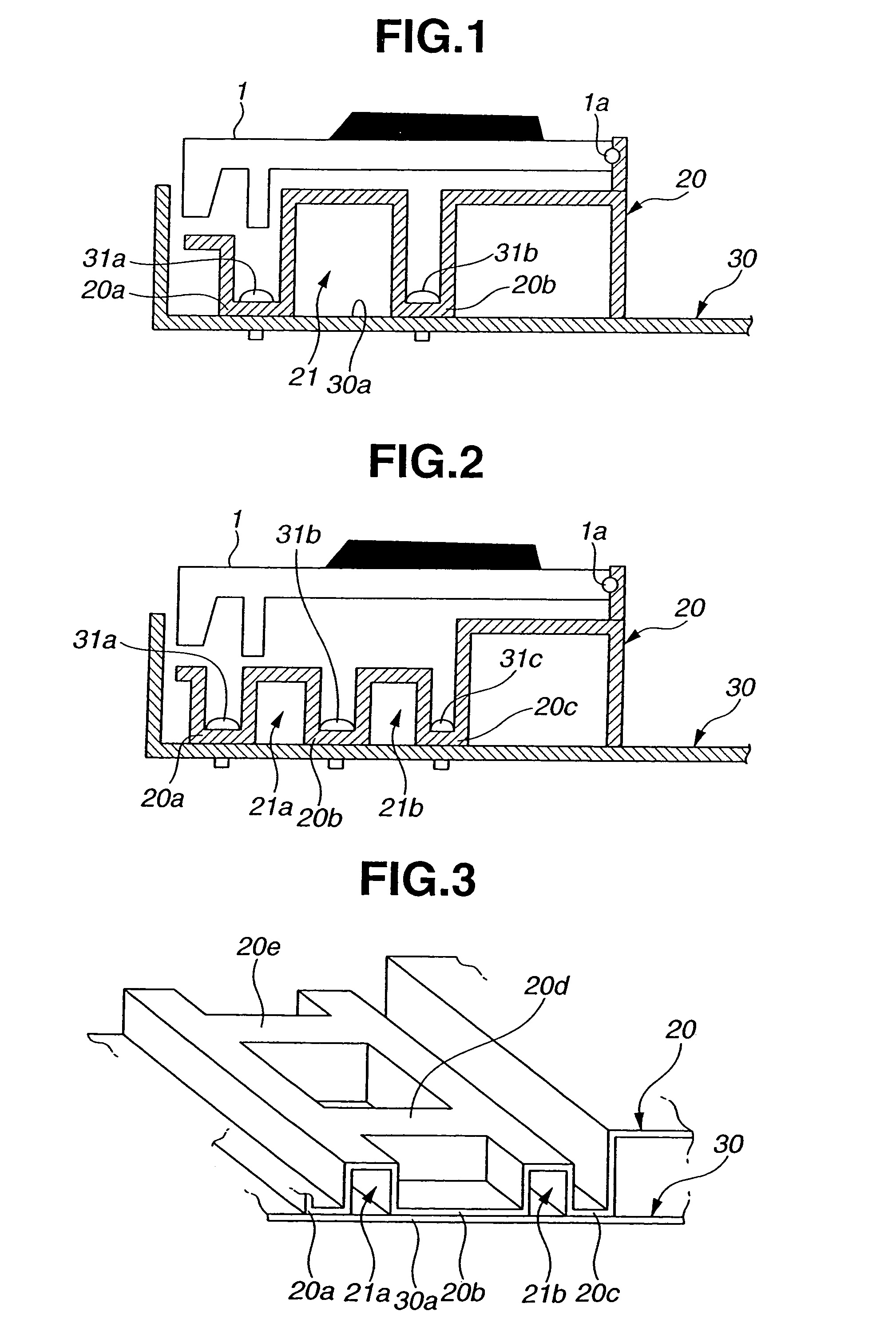
[0023]FIG. 1 is a sectional side view schematically showing relevant portions of a frame structure of a keyboard apparatus in accordance with the present invention, which is employed in an electronic musical instrument. A plurality of keys 1 for performance operation are pivotably mounted via supporting points (or pivot shaft) on predetermined positions of a frame 20 formed of synthetic resin, in the same manner as conventionally known in the art. The frame 20 has a continuous surface defining a channel-shaped concave section 21, which extends in a direction where the keys 1 are arranged on and along the frame 20. Body section (casing) 30 for mounting therein the frame 20 has a supporting surface 30a that contacts wall regions of the frame 20 at opposite sides of an opening portion of the concave section 21 (hereinafter referred to as “opposite sides 20a and 20b” of the opening portion) when the frame 20 is duly mounted in place in the body section 30. In other words, the channel-sh...

second embodiment

[0030]FIG. 3 is a perspective view schematically showing a modification of the frame structure in the keyboard apparatus of the present invention. The frame 20 of the modified frame structure includes connecting portions 20d and 20e that interconnect the two parallel channel-shaped concave sections 21a and 21b in the depth direction of the keys. Each of these connecting portions 20d and 20e too may be formed as a tubular portion having a downwardly-opening channel-like concave sectional shape, and opposite sides of the opening portion may be supported in abutment against the supporting surface 30a of the body section 30. Thus, the modified frame structure constitutes a ladder frame structure as a whole, which can prevent relative twisting between two tubular bodies, formed by the channel-shaped concave sections 21a and 21b, and even further enhance the rigidity of the keyboard apparatus. The connecting portions 20d and 20e may be integrally formed with other portions, such as the ch...


PUM


Abstract

Frame on which a plurality of keys are operably mounted has a continuous surface defining a channel-shaped concave section extending in a direction where the keys are arranged, and a body section in which the frame is mounted has a supporting surface that contacts opposite sides of an opening of the channel-shaped concave section of the frame. The opposite sides of the opening of the channel-shaped concave section of the frame are fixed to the supporting surface of the body section. Thus, a closed-section structure is formed by the channel-shaped concave section of the frame and the supporting surface of the body section, which constitutes a semi monocoque structure extending in the key-arranged direction. Such a structure can enhance bending rigidity and twisting rigidity relative to the key-arranged direction.

Description

BACKGROUND OF THE INVENTION[0001]The present invention relates generally to music-performing keyboard apparatus applicable to electronic musical instruments etc. and more particularly to an improved keyboard apparatus having an increased overall rigidity.[0002]Music-performing keyboard apparatus, applied to electronic musical instruments etc., basically comprise a plurality of performing keys arranged side by side in a horizontal direction, Thus, the keyboard apparatus are generally elongated in shape in a direction of scale notes (i.e., key-arranged direction), so that a force produced by depression of a key during a performance acts in a direction to bend a horizontally-elongated apparatus casing as illustrated in FIG. 7. Further, when the keyboard apparatus are lifted for transfer of the keyboard apparatus, a force acts in a direction to twist the horizontally-elongated apparatus casing. For these reasons, it is desirable that the keyboard apparatus be designed to enhance the rig...

Claims


Application Information

Patent Timeline
Patent Type & Authority Patents(United States)
IPC IPC(8): G10D13/02
CPCG10H1/34
Inventor NISHIDA, KENICHI
Owner YAMAHA CORP
Why Eureka
Try Eureka