
Omnidirectional tilt and vibration sensor

a technology of vibration sensor and tilt switch, which is applied in the field of sensors, can solve the problems of increased cost of mercury containing products, tilt switch generally is not useful in detecting minimal motion, and mercury use regulation

Active Publication Date: 2008-02-05
SIGNALQUEST LLC
View PDF24 Cites 105 Cited by
  • Summary
  • Abstract
  • Description
  • Claims
  • Application Information

AI Technical Summary

Benefits of technology

"The present invention provides an omnidirectional tilt and vibration sensor and a method of construction. The sensor has a first electrically conductive element, a second electrically conductive element, and an electrically insulative element connected to the first and second elements. The sensor also contains a plurality of electrically conductive weights located within a cavity of the sensor. The method involves fitting the first element into the hollow center of the insulative member, positioning the weights within the hollow center, and fitting the second element into the hollow center of the insulative member. The technical effects of this invention include improved accuracy and reliability in measuring tilt and vibration, as well as simplified construction and assembly processes."

Problems solved by technology

Unfortunately, it has been proven that use of Mercury may lead to environmental concerns, thereby leading to regulation on Mercury use and increased cost of Mercury containing products, including switches.
Unfortunately, tilt switches generally are not useful in detecting minimal motion, regardless of the tilt angle.
Unfortunately, the many portions of the '979 patent vibration switch results in more time required for assembly, in addition to higher cost.
Thus, a heretofore unaddressed need exists in the industry to address the aforementioned deficiencies and inadequacies.

Method used


Image

  • Omnidirectional tilt and vibration sensor
  • Omnidirectional tilt and vibration sensor
  • Omnidirectional tilt and vibration sensor

Examples


Embodiment Construction

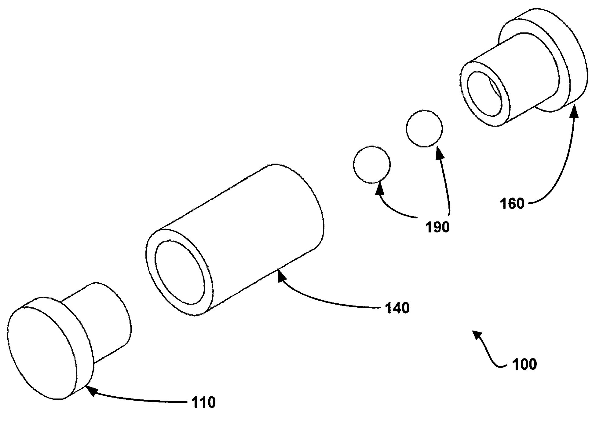
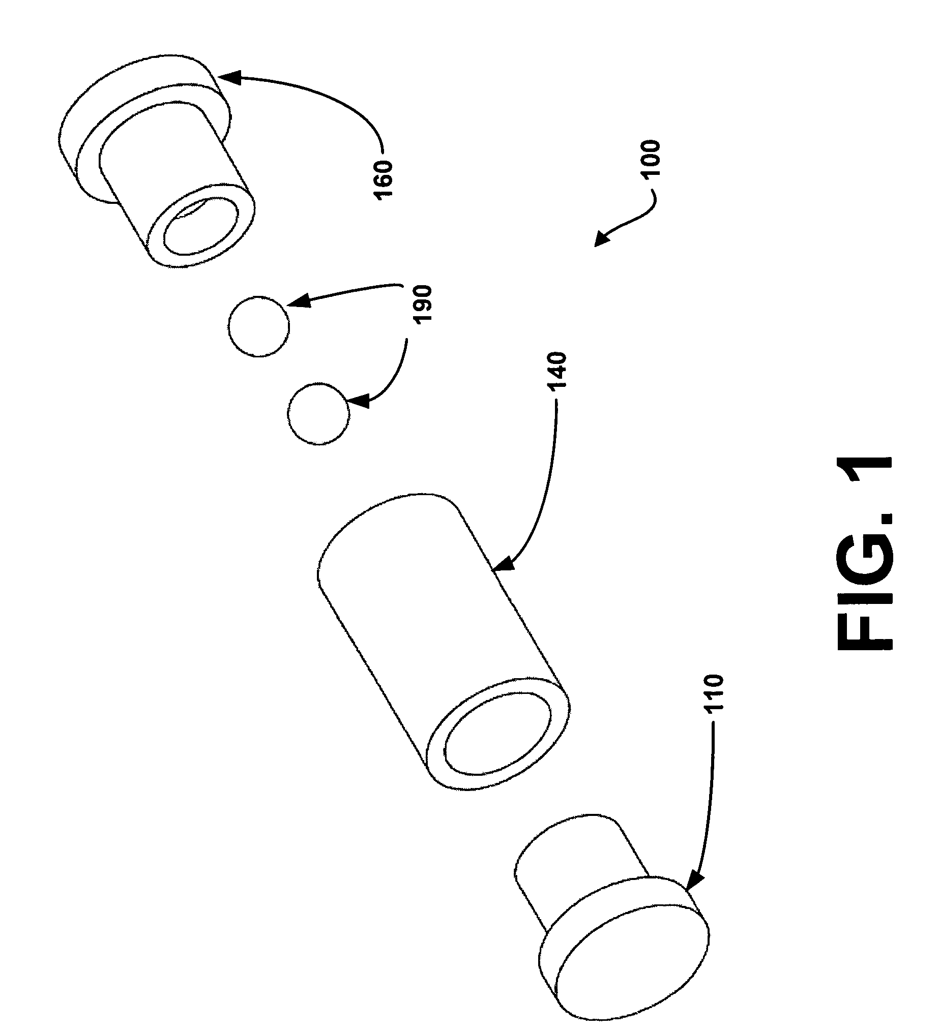
[0024]The following describes an omnidirectional tilt and vibration sensor. The sensor contains a minimal number of cooperating parts to ensure ease of assembly and use. FIG. 1 is an exploded perspective side view of the present omnidirectional tilt and vibration sensor 100 (hereafter, “the sensor 100”), in accordance with a first exemplary embodiment of the invention.

[0025]Referring to FIG. 1, the sensor 100 contains a first end cap 110, a central member 140, a second end cap 160, and multiple weights embodied as a pair of conductive balls 190 that are spherical in shape (hereafter, conductive spheres). The first end cap 110 is conductive, having a proximate portion 112 and a distal portion 122. Specifically, the first end cap 110 may be constructed from a composite of high conductivity and / or low reactivity metals, a conductive plastic, or any other conductive material.

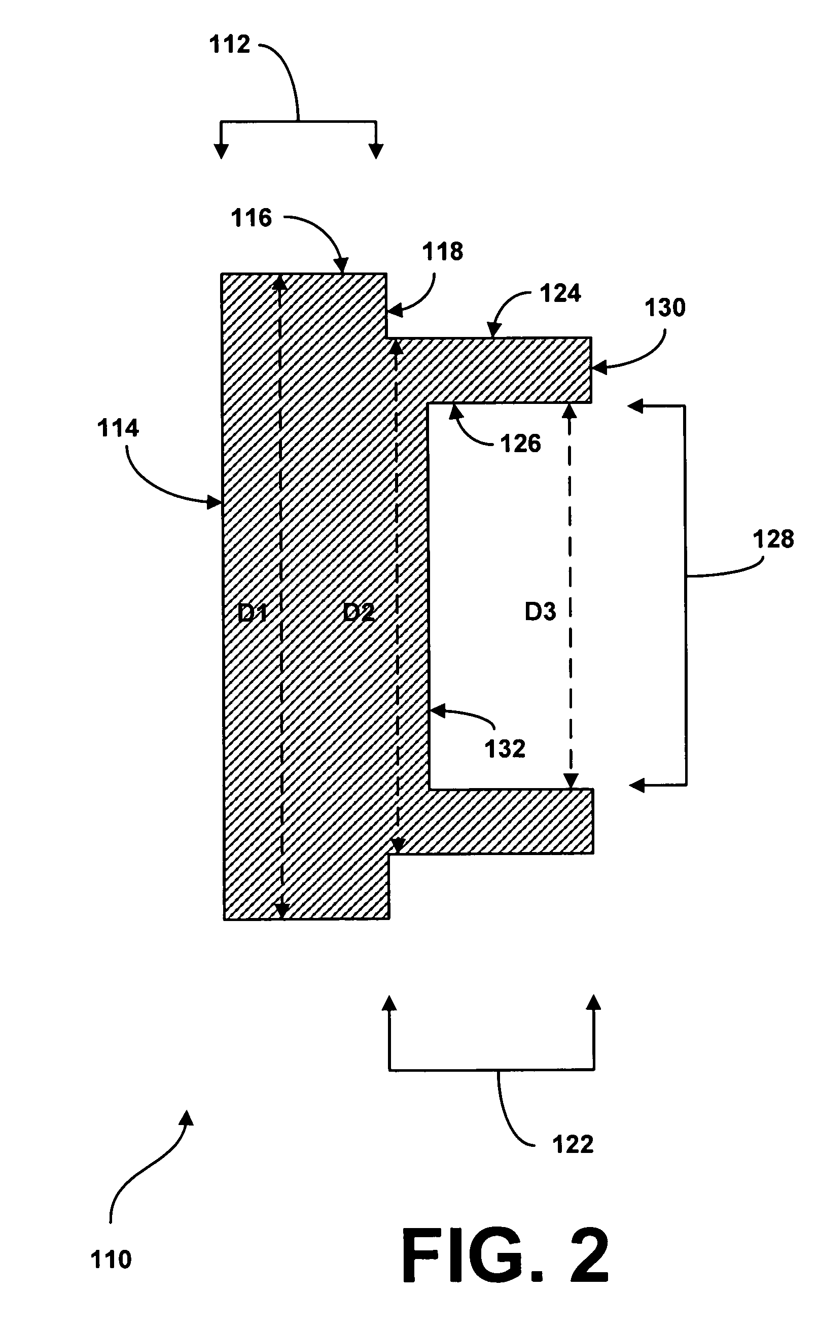
[0026]FIG. 2 is a cross-sectional side view of the first end cap 110 which may be referred to for a better unders...


PUM


Abstract

A sensor contains a first electrically conductive element, a second electrically conductive element, and an electrically insulative element connected to the first electrically conductive element and the second electrically conductive element. The sensor also contains a plurality of electrically conductive weights located within a cavity of the sensor, wherein the cavity is defined by at least one surface of the first electrically conductive element, at least one surface of the electrically insulative element, and at least one surface of the second electrically conductive element.

Description

CROSS-REFERENCE TO RELATED APPLICATIONS[0001]The present application is a continuation of U.S. patent application Ser. No. 11 / 037,497, filed Jan. 18, 2005 now U.S. Pat. No. 7,067,748, and having the title “OMNIDIECTIONAL TILT AND VIBRATION SENSOR,” the entire disclosure of which is incorporated wherein by reference.[0002]The present application claims priority to copending U.S. patent application Ser. No. 11 / 037,497, filed Jan. 18, 2005, and having the title “OMNIDIECTIONAL TILT AND VIBRATION SENSOR.”FIELD OF THE INVENTION[0003]The present invention is generally related to sensors, and more particularly is related to an omnidirectional tilt and vibration sensor.BACKGROUND OF THE INVENTION[0004]Many different electrical tilt and vibration switches are presently available and known to those having ordinary skill in the art. Typically, tilt switches are used to switch electrical circuits ON and OFF depending on an angle of inclination of the tilt switch. These types of tilt switches ty...

Claims


Application Information

Patent Timeline
Patent Type & Authority Patents(United States)
IPC IPC(8): H01H35/02
CPCH01H35/144H01H35/02H01H1/5833H01H1/66
Inventor KELLEY, JR., WHITMORE B.BLADES, BRIAN
Owner SIGNALQUEST LLC
Learn More