
Advertisement distribution system for distributing targeted advertisements in television systems

Inactive Publication Date: 2008-02-05
PRIME RES ALLIANCE E LLC
View PDF129 Cites 114 Cited by
  • Summary
  • Abstract
  • Description
  • Claims
  • Application Information

AI Technical Summary

Benefits of technology

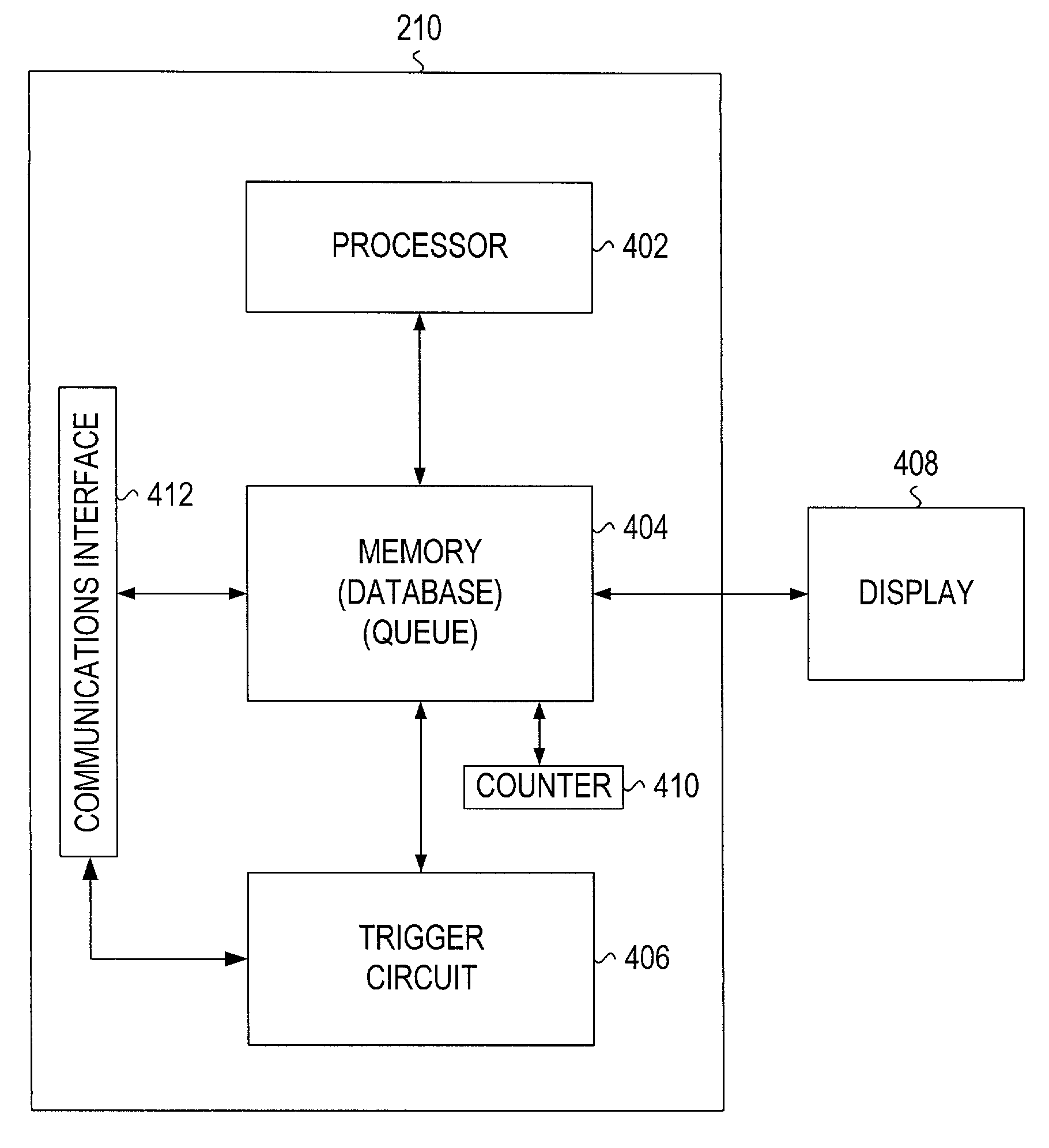
[0006]This invention is targeted at providing a system and method for distributing advertisements (ads) in a television network, e.g., a cable-based network or a satellite network. In particular, the invention is directed at providing refreshed advertisements to a set-top box (STB), wherein the STB has a memory and stores the refreshed advertisements preferably in a queue, the queue describing the order in which the advertisements should be inserted. A system and method of this invention provides a “client” application that resides on the subsc

Problems solved by technology

In addition, once a particular advertising break has been filled with an advertisement, the television broadcaster can no longer sell that space in the broadcast stream.
Because the advertisements on a particular channel are seen by every viewer tuned to the particular channel in a conventional television system, the advertisements in a conventional television broadcast system cannot be targeted to a particular portion of the audience or even to a particular individual.
Therefore, the television broadcast operator may only derive a limited predetermined amount of advertising revenue from any particular advertisement spot.
The problem with advertisements on a conventional television broadcasting system for the advertiser is that each advertiser is interested in reaching only one or more subsets of the total viewing audience because not all members of the viewing audience may be desirable candidates for receiving a particular advertisement.
Therefore, the advertisement viewed by the other 60-80% of the audience, which are not prime candidates, represents a large amount of wasted spending by the advertiser.

Method used


Image

  • Advertisement distribution system for distributing targeted advertisements in television systems
  • Advertisement distribution system for distributing targeted advertisements in television systems
  • Advertisement distribution system for distributing targeted advertisements in television systems

Examples


Embodiment Construction

[0022]In describing a preferred embodiment of the invention illustrated in the drawings, specific terminology will be used for the sake of clarity. However, the invention is not intended to be limited to the specific terms so selected, and it is to be understood that each specific term includes all technical equivalents which operate in a similar manner to accomplish a similar purpose.

[0023]With reference to the drawings, in general, and FIGS. 1 through 11 in particular, the method and system of the present invention is disclosed.

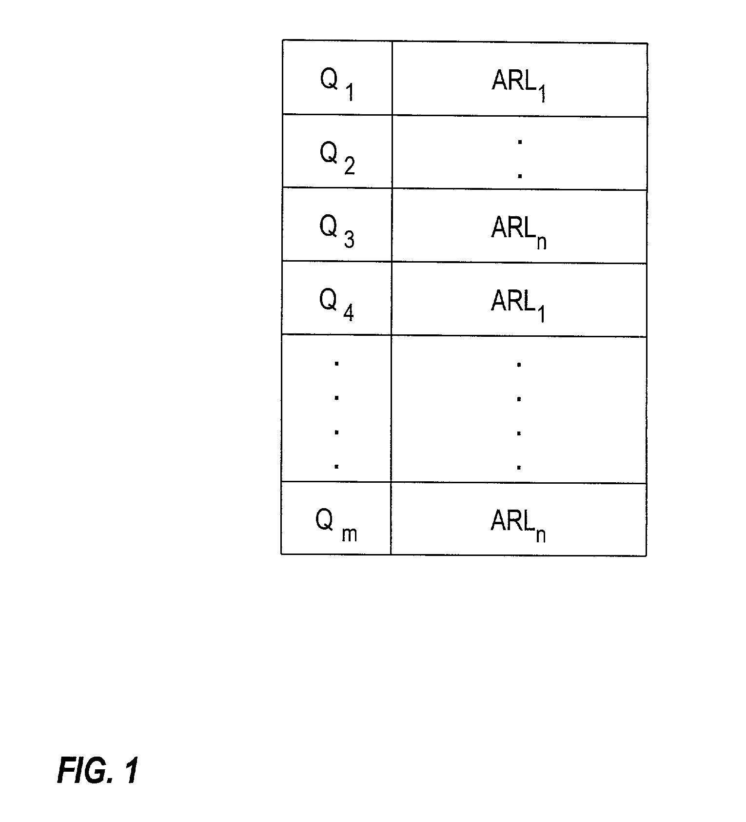
[0024]In advanced television systems, such as digital cable and Digital Subscriber Line (DSL) systems, advertisements (ads) no longer need to be received from broadcasters, instead the ads may be stored locally at subscriber equipment. For example, a plurality of ads may be stored in memory in the subscriber equipment. The location of each ad is identified by a pointer, known as an ad resource locator (ARL). For example, if n ads are stored in memory, they ...


PUM


Abstract

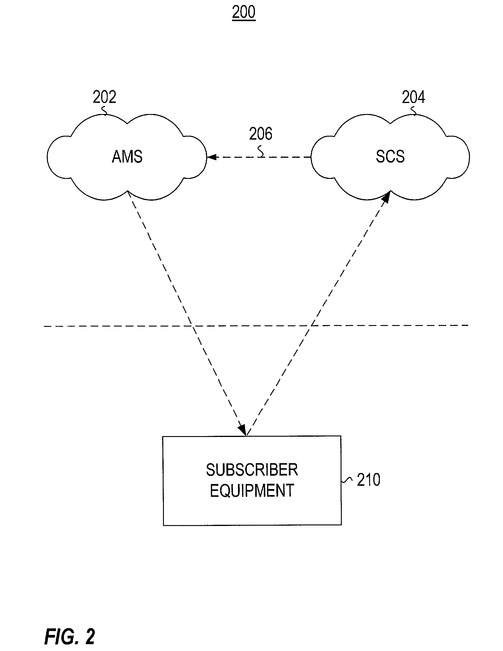
Providing refreshed advertisements to subscriber equipment 210, such as a set-top box. A “client” application runs on the subscriber equipment 210 and includes a queue 404 for storing targeted advertisements, a processor 402 for monitoring the display of each advertisement to the subscriber, a counter 410 for counting each display, and a trigger circuit 406 for initiating an advertisement download each time it is determined that the queue of advertisements stored at the client application has reached a low-level threshold. An advertisement management system 202 provides advertisements to the client application. These advertisements may be network-based advertisements or may be targeted to each individual subscriber, based on a subscriber profile that is provided by a subscriber characterization system 204.

Description

[0001]This patent application claims benefit under 35 USC §1.19(e) of Provisional application No. 60 / 229,156 filed on Aug. 31, 2000 entitled Method and System for Addressable and Program Independent Advertising, which is incorporated herein by reference.BACKGROUND OF THE INVENTION[0002]Traditional broadcast television is a single orientation point to a plurality of destination points system in which the same television signal is broadcast to each person viewing a particular station. Thus, each person viewing a particular channel will necessarily view the same programming content as well as the same advertisements embedded in the programming content. For most broadcast medium industries, such as television, advertising revenues may be the sole source of revenues for the television broadcaster. In a conventional television broadcast system, many advertisers compete for the opportunity to place their advertisement in the advertisement breaks between the programming content. In addition...

Claims


Application Information

Patent Timeline
IPC IPC(8): H04N7/10H04N7/173G06Q30/02H04H1/00H04H20/40H04H60/27H04H60/66H04N5/445H04N7/16H04N21/258H04N21/262H04N21/2668H04N21/426H04N21/433H04N21/45H04N21/454H04N21/478H04N21/81H04N21/84H04N21/858
CPCG06Q30/02H04H60/27H04H60/66H04N5/44543H04N7/165H04N7/17354H04N7/17363H04N21/25883H04N21/25891H04N21/26233H04N21/26241H04N21/2668H04N21/42684H04N21/4331H04N21/4532H04N21/454H04N21/812H04N21/84H04N21/8586H04H20/40H04N21/478H04N21/47
Inventor ELDERING, CHARLES A.GILL, KOMLIKA K.
Owner PRIME RES ALLIANCE E LLC
Learn More