Phosphor-converted LED devices having improved light distribution uniformity

a technology of led devices and phosphors, which is applied in the direction of semiconductor devices, semiconductor/solid-state device details, electrical devices, etc., can solve the problems of unwanted wide white color bin spread, phosphor migration is partially impeded, and parts of the sinking phosphor that clear the outer edges of the top surface of the led may further sink below that surfa

Active Publication Date: 2008-02-12
DOCUMENT SECURITY SYST
View PDF17 Cites 44 Cited by
  • Summary
  • Abstract
  • Description
  • Claims
  • Application Information

AI Technical Summary

Problems solved by technology

Unfortunately, the non-unity of both the physical positioning and the functional operation of these photonic sources generally results in non-uniformity in the additive photonic emissions from conventional phosphor-converted LED devices, producing an unwanted wide white color bin spread.
This migration often leads to uneven layering of the phosphor over the LED, which results in a phosphor-converted LED device producing a wide white color bin spread.
As an example of problems associated with this conventional fabrication method, if the shape of the LED is a rectangular prism, then the phosphor may sink to the bottom of the phosphor-encapsulant dispersion to the point that further migration of the phosphor is partially impeded by the LED itself.
In particular, portions of the sinking phosphor that clear the outer edges of the top surface of the LED may further sink below that surface.
Upon stimulation of electroluminescent emissions from the LED itself, this decreased thickness may result in reduced capacity by the phosphor near the outer edges to convert the photons emitted by the LED by stimulated emissions.
This reduced capacity imbalances the desired ratio between blue and yellow photons emitted from the phosphor-converted LED device in regions over the outer edges, because the yellow photonic emissions there are reduced.
This blue halo constitutes a non-uniformity in the light output from the phosphor-converted LED device that may be both aesthetically and functionally undesirable in use of the device.

Method used


Image

  • Phosphor-converted LED devices having improved light distribution uniformity
  • Phosphor-converted LED devices having improved light distribution uniformity
  • Phosphor-converted LED devices having improved light distribution uniformity

Examples


Embodiment Construction

[0020]In the following description of various implementations, reference is made to the accompanying drawings that form a part of this disclosure, and which show, by way of illustration, specific implementations in which the invention may be practiced. Other implementations may be utilized and structural changes may be made without departing from the scope of the present invention.

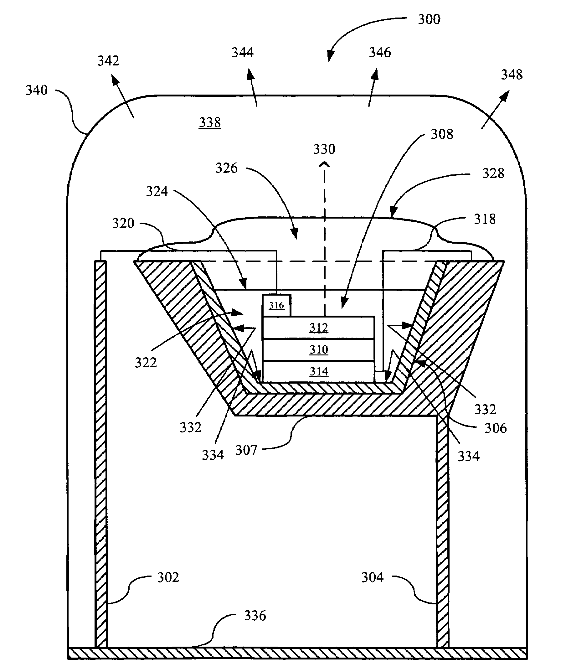
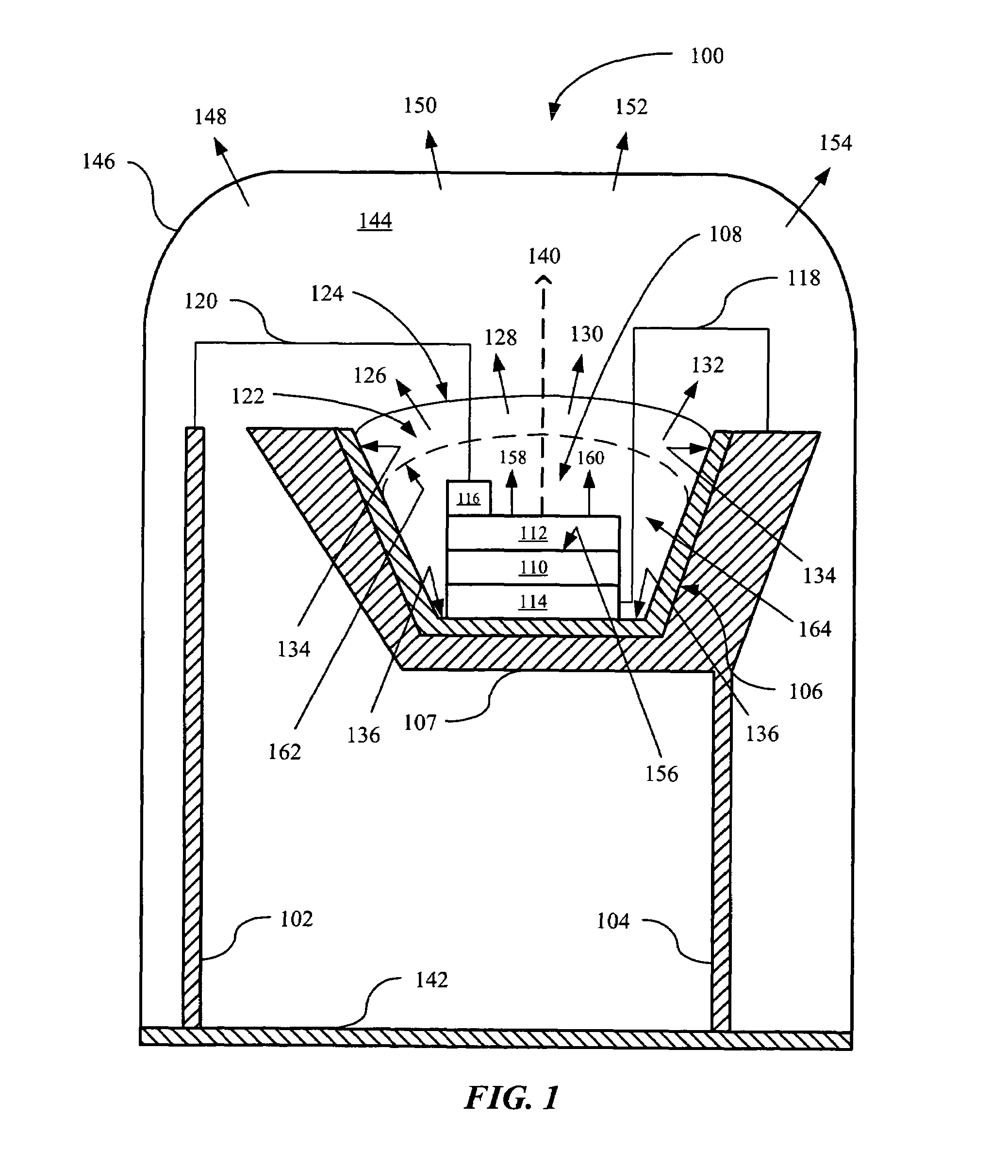
[0021]In FIG. 1, a cross-sectional view of an example of an implementation of a new phosphor-converted LED device (“NPCLD”) 100 is shown in accordance with the invention. The NPCLD 100 includes an anode 102 and a cathode 104. The cathode 104 includes a concave (i.e., bowl and / or cup-shaped) base housing 106 formed of an electrical insulator and supported on a frame 107, in which an LED 108 is placed. The frame 107 may be integrated with the cathode 104, and may be fabricated, for example, from lead. It will be understood by those skilled in the art that the frame 107 may alternatively be any form of printe...


PUM


Abstract

A New Phosphor-converted LED Device (“NPCLD”) is disclosed. The NPCLD may include a lens over a phosphor body, in which the lens and the phosphor body each have a substantially convex upper surface. The NPCLD may alternatively include first and second lenses, the first lens having a substantially flat interface with a phosphor body.

Description

BACKGROUND OF THE INVENTION[0001]Phosphor-converted light emitting diode (“LED”) devices are useful for generating light output having actual and perceived spectral characteristics that differ from the actual spectral characteristics of the LEDs themselves. For example, the advent of blue LEDs was a key development in the quest for LED devices emitting apparently white light, as potential replacements for incandescent and fluorescent bulbs. Blue LEDs have been integrated with yellow phosphors to emit blue and yellow photons in ratios that are perceived by the human eye as white light. Although these photonic emissions do not span the complete visible spectrum and therefore are not actually equivalent to sunlight, they appear to be white and thus may be effectively utilized, for example in lighting applications. Since LED devices may convert electricity into photonic emissions more efficiently than incandescent and fluorescent bulbs, the potential benefits of LED use for lighting and...

Claims


Application Information

Patent Timeline
Patent Type & Authority Patents(United States)
IPC IPC(8): H01L29/22H01L23/00H01L29/04H01L33/00H01L33/50H01L33/54H01L33/62
CPCH01L33/508H01L33/54H01L33/62H01L2224/48247H01L2224/48257H01L2224/49107H01L2924/3011H01L2924/00H01L2924/181H01L2224/48095H01L2924/19107H01L2924/00012H01L33/50
Inventor PANG, SIEW ITLEE, MENG EELEE, KIAN SHINOON, SU LINYEOH, HONG HUAT
Owner DOCUMENT SECURITY SYST
Why Eureka
Try Eureka