Quantum dense coding system

a coding system and quantum technology, applied in the field of quantum dense coding system, can solve the problems of inefficiency easy interception and detection of typical optical communication system,

Inactive Publication Date: 2008-02-12
THE UNITED STATES OF AMERICA AS REPRESENTED BY THE SECRETARY OF THE NAVY
View PDF9 Cites 16 Cited by
  • Summary
  • Abstract
  • Description
  • Claims
  • Application Information

AI Technical Summary

Problems solved by technology

Typical optical communication systems are susceptible to interception and detection.
In addition, typical optical com

Method used


Image

  • Quantum dense coding system
  • Quantum dense coding system
  • Quantum dense coding system

Examples


Embodiment Construction

[0006]The present invention is directed to Quantum Dense Coding Systems (QDCS). Although the invention is described with respect to specific embodiments, the principles of the invention, as defined by the claims appended herein, can obviously be applied beyond the specifically described embodiments of the invention described herein. Moreover, in the description of the present invention, certain details have been left out in order to not obscure the inventive aspects of the invention. The details left out are within the knowledge of a person of ordinary skill in the art.

[0007]The drawings in the present application and their accompanying detailed description are directed to merely exemplary embodiments of the invention. To maintain brevity, other embodiments of the invention that use the principles of the present invention are not specifically described in the present application and are not specifically illustrated by the present drawings.

DEFINITIONS

[0008]The following definitions a...


PUM


Abstract

A Quantum Dense Coding System. The system includes a source, a transmitter and a receiver. The source is capable of down-converting a pump photon into a signal photon and an idler photon and outputting probability amplitudes, the signal photon and the idler photon, wherein the signal photon and the idler photon have an equal probability of outputting to a transmission channel and a reception channel. The transmitter is capable of receiving probability amplitudes, signal photons and idler photons from the transmission channel; and selectively changing vertical and horizontal phases of probability amplitudes of signal photons and idler photons; and outputting probability amplitudes, signal photons and idler photons. The receiver is capable of receiving probability amplitudes, signal photons and idler photons from the reception channel and the transmitter; and identifying vertical and horizontal phase changes created by the transmitter. A method for the system is also described.

Description

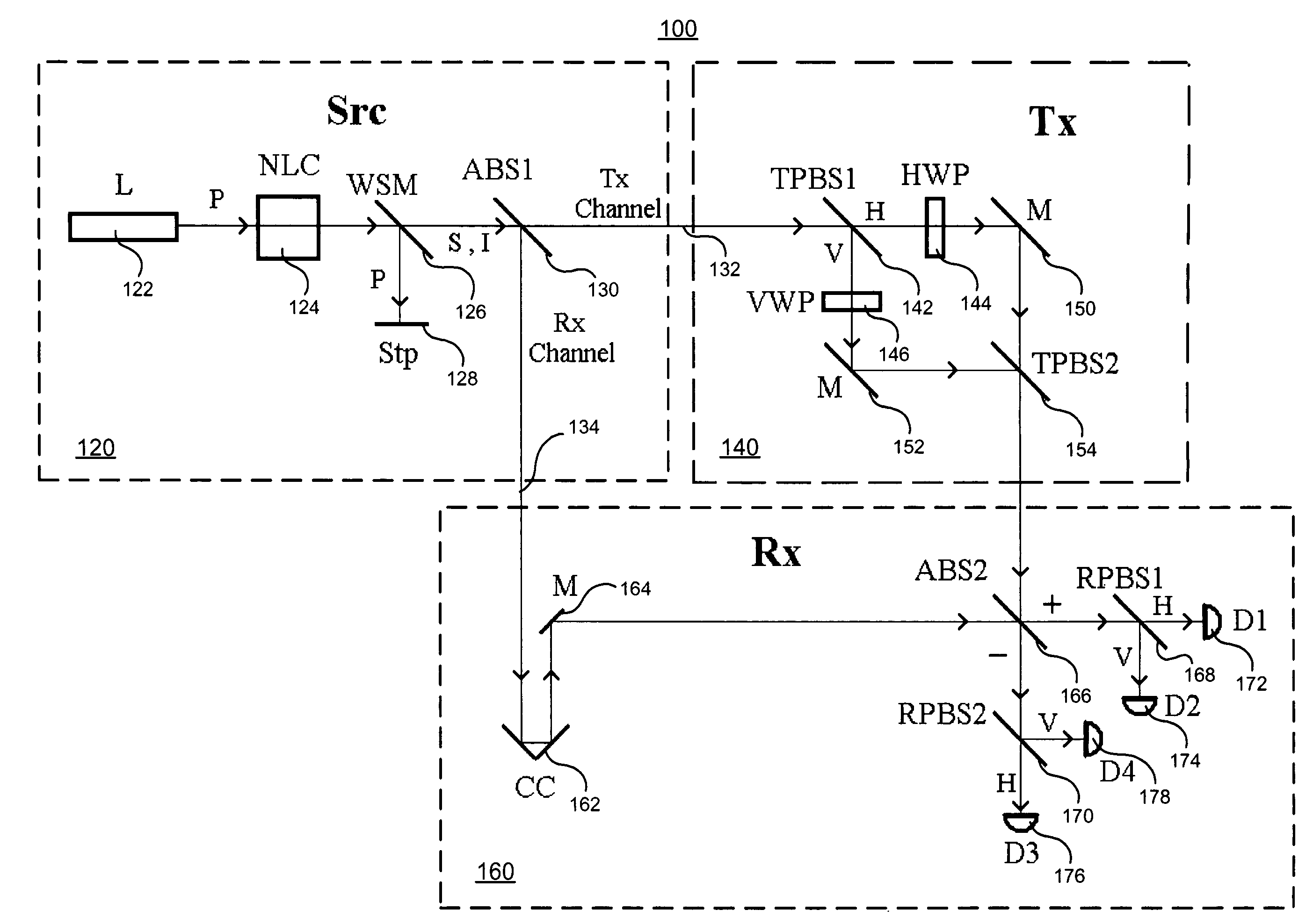
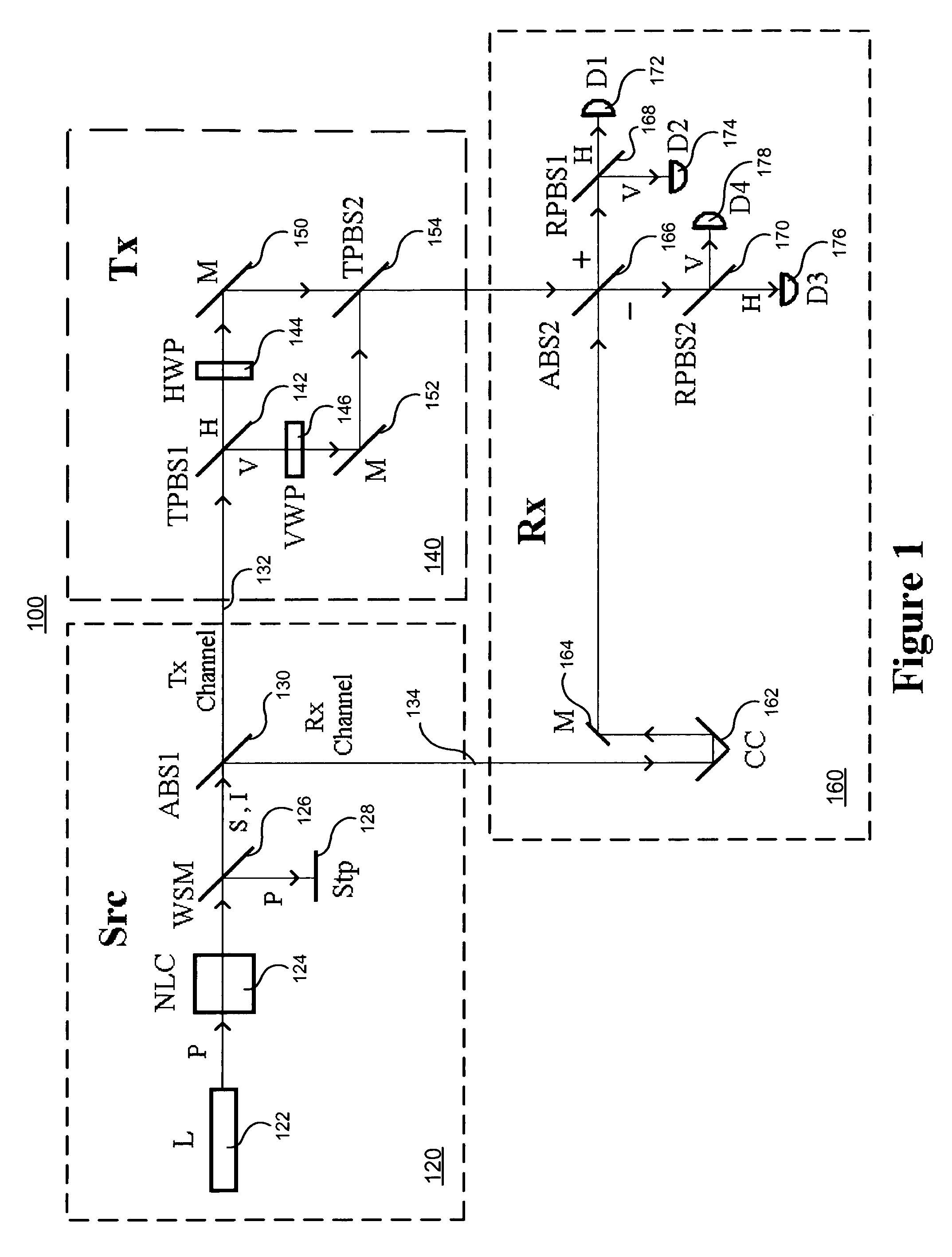
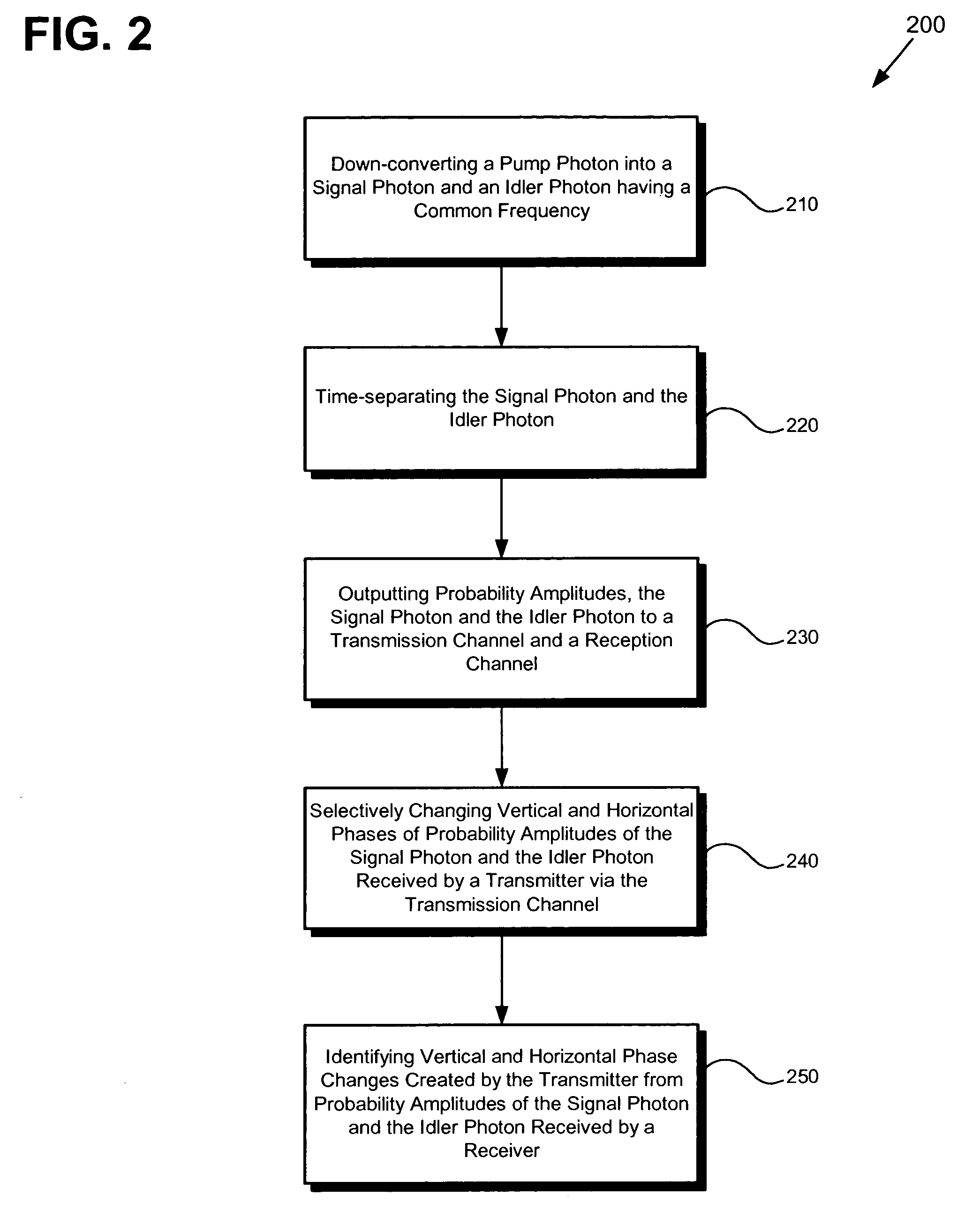
BACKGROUND OF THE INVENTION[0001]The present invention is generally in the field of optical communication systems.[0002]Typical optical communication systems are susceptible to interception and detection. In addition, typical optical communication systems are inefficient (e.g., can transmit, at most, only one bit of information per transmitted photon).[0003]A need exists for optical communication systems having low probability of interception (LPI), low probability of detection (LPD) and increased efficiency.BRIEF DESCRIPTION OF THE DRAWINGS[0004]FIG. 1 is a block diagram of one embodiment of a QDC system.[0005]FIG. 2 is a flowchart of an exemplary method of one embodiment of a QDC system.DETAILED DESCRIPTION OF THE INVENTION[0006]The present invention is directed to Quantum Dense Coding Systems (QDCS). Although the invention is described with respect to specific embodiments, the principles of the invention, as defined by the claims appended herein, can obviously be applied beyond t...

Claims


Application Information

Patent Timeline
IPC IPC(8): H04B10/00H04K1/00
CPCH04B10/30H04B10/70
Inventor ROBERTS, MARK W.LASHER, MARKHAM E.
Owner THE UNITED STATES OF AMERICA AS REPRESENTED BY THE SECRETARY OF THE NAVY
Why Eureka
Try Eureka