Unlock instant, AI-driven research and patent intelligence for your innovation.

Test pattern generating apparatus, circuit designing apparatus, test pattern generating method, circuit designing method, test pattern generating program and circuit designing program

a test pattern and circuit design technology, applied in the field of test pattern generating apparatus, circuit designing apparatus, test pattern generating method, circuit designing method, etc., can solve the problems of explosive increase in and achieve the effect of reducing processing time and occupied memory area for generating test patterns

Inactive Publication Date: 2008-02-19
FUJITSU LTD
View PDF23 Cites 3 Cited by
  • Summary
  • Abstract
  • Description
  • Claims
  • Application Information

AI Technical Summary

Benefits of technology

The present invention provides a test pattern generating apparatus, circuit designing apparatus, test pattern generating method, and test pattern generating program that can reduce the processing time and memory area required for generating test patterns. This is achieved by preparing a list of flip flops for each functional block in the circuit, and setting up correspondence between the test pattern generating object blocks and the test pattern copying object blocks. The test pattern generating apparatus reads in circuit data, divides it into functional blocks, and prepares a list of flip flops for each block. The test pattern generating method then generates a test pattern for each object block and copies it as the test pattern for the corresponding object block. This reduces the processing time and memory area required for generating test patterns.

Problems solved by technology

Since the number of functional blocks and that of gates mounted in an LSI are ever increasing, there arises a problem that the processing time and the occupied memory area increase explosively if test patterns are generated for all the functional blocks.

Method used


Image

  • Test pattern generating apparatus, circuit designing apparatus, test pattern generating method, circuit designing method, test pattern generating program and circuit designing program
  • Test pattern generating apparatus, circuit designing apparatus, test pattern generating method, circuit designing method, test pattern generating program and circuit designing program
  • Test pattern generating apparatus, circuit designing apparatus, test pattern generating method, circuit designing method, test pattern generating program and circuit designing program

Examples


Embodiment Construction

[0029]Now, the present invention will be described by referring to the accompanying drawings that illustrate preferred embodiments of the invention.

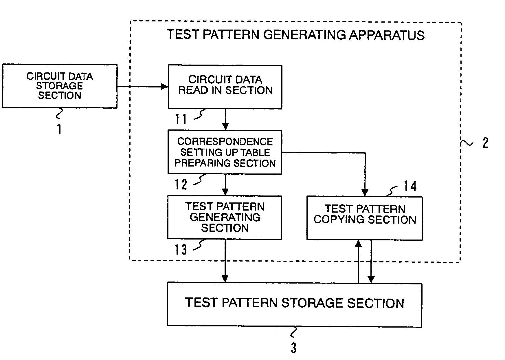
[0030]Firstly, an embodiment of test pattern generating apparatus according to the invention will be described for its configuration. FIG. 1 is a schematic block diagram of the embodiment of test pattern generating apparatus. In FIG. 1, the components that are identical with or similar to those of the known apparatus of FIG. 7 are denoted respectively by the same reference symbols and will not be described here any further. FIG. 1 illustrates a test pattern generating apparatus 2 according to the invention, whereas FIG. 7 illustrates a known test pattern generating apparatus 102. It will be seen by comparing the known test pattern generating apparatus 102 and the test pattern generating apparatus 2 according to the invention, the latter apparatus comprises a correspondence setting up table preparing section 12 and a test pattern copying ...


PUM


Abstract

A test pattern generating apparatus comprises a circuit data read in section 11 that divides circuit data into a plurality of functional blocks, a correspondence setting up table preparing section 12 that sorts the plurality of functional blocks into test pattern generating object blocks and test pattern copying object blocks that are configurationally identical with the test pattern generating object blocks and sets up correspondence of the test pattern generating object blocks to the test pattern copying object blocks, a test pattern generating section 13 that generates a test pattern of each of the test pattern generating object blocks and a test pattern copying section 14 that copies the test pattern of each of the test pattern copying object blocks and uses it as test pattern of the test pattern copying object block.

Description

BACKGROUND OF THE INVENTION[0001]1. Field of the Invention[0002]This invention relates to a test pattern generating apparatus, a circuit designing apparatus, a test pattern generating method, a circuit designing method, a test pattern generating program and a circuit designing program for generating test patterns to be used for judging if a manufactured LSI is acceptable or unacceptable from the circuit data of the designed LSI.[0003]2. Description of Related Art[0004]Firstly, a known test pattern generating apparatus will be described by referring to FIG. 7 of the accompanying drawings. FIG. 7 is a schematic block diagram of a known test pattern generating apparatus, showing its configuration. The test pattern generating apparatus 102 comprises a circuit data read in section 11 and a test pattern generating section 13. The circuit data read in section 11 is connected to an external circuit data storage section 1 while the test pattern generating section 13 is connected to an extern...

Claims


Application Information

Patent Timeline
Patent Type & Authority Patents(United States)
IPC IPC(8): G01R31/28
CPCG01R31/31813G01R31/318307
Inventor KANUMA, AKIRA
Owner FUJITSU LTD
Features
  • R&D
  • Intellectual Property
  • Life Sciences
  • Materials
  • Tech Scout
  • Unparalleled Data Quality
  • Higher Quality Content
  • 60% Fewer Hallucinations
Learn More