Pressure sensor and method for operating a pressure sensor

a pressure sensor and pressure sensor technology, applied in the direction of fluid pressure measurement, fluid pressure measurement by electric/magnetic elements, instruments, etc., can solve the the comparatively high capacity between substrate and membrane or counter-structure is a disadvantage of prior art microphones, and the manufacturing method is further simplified. , to achieve the effect of reducing complexity, improving manufacturing yield and low chip area

Active Publication Date: 2005-12-01
INFINEON TECH AG
View PDF5 Cites 35 Cited by
  • Summary
  • Abstract
  • Description
  • Claims
  • Application Information

AI Technical Summary

Benefits of technology

[0015] The advantages of this reduction in complexity are a low chip area of the entire pressure sensor system, the system of the actual pressure sensor and the circuit for evaluating a pressure sensor signal, an increased manufacturing yield and accompanying cost reduction for manufacturing the pressure sensor system connected thereto.
[0016] The complexity for testing the pressure sensor is also diminished by the increased sensitivity thereof.
[0017] In a preferred embodiment, the membrane comprises passages so that it only responds to dynamic pressure but not to static pressure.

Problems solved by technology

Apart from that, the increasing pressure on the cost of these devices, such as, for example, mobile telephones or devices having voice recognition systems, requires further simplification of the manufacturing methods for microphones.
The comparatively high capacity between substrate and membrane or counter-structure is a disadvantage of prior art microphones.
The proportional sensitivity, i.e. the capacity change relative to the overall capacity, divided by a change in sound pressure, is thus limited due to the high static capacity.
A small ratio of the change in capacity to the overall capacity results in the requirement of a complicated signal processing.
This, in turn, means that the signal processing stages downstream of the actual silicon microphone, due to the small ratio, are complicated and thus expensive and consume lots of chip area, which, in turn, limits the price reduction when manufacturing the microphone system of a silicon microphone having an integrated evaluation circuit in large numbers.

Method used


Image

  • Pressure sensor and method for operating a pressure sensor
  • Pressure sensor and method for operating a pressure sensor
  • Pressure sensor and method for operating a pressure sensor

Examples


Embodiment Construction

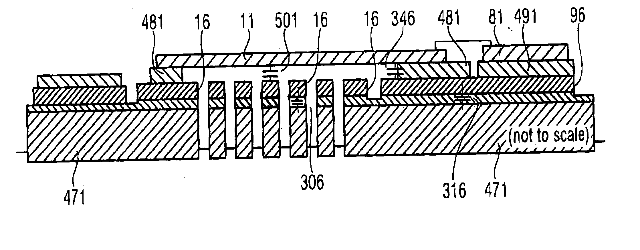
[0032]FIG. 8 shows an embodiment of a pressure sensor according to the present invention. A pressure sensor 1 can be seen there. The pressure sensor comprises a membrane terminal 81, a counter-structure terminal 91, a guard ring 96 which is only shown schematically here, and a guard ring terminal 101.

[0033] A change in pressure coming from outside, resulting in a deflection of a membrane structure 11 which will be explained below, enters via a pressure inlet hole 377. The deflection of the membrane structure 11 results in a change in capacity of the capacity between the membrane terminal 81 and the counter-structure terminal 91.

[0034] A constant direct voltage is applied to the counter-structure terminal 91 and a ground terminal 386. The voltage divider 396a, 396b results in setting the operating point of the pressure sensor assembly, the potential for the operating point being tapped exactly between the two voltage divider resistors 396a, 396b.

[0035] A change in the capacity bet...


PUM

PropertyMeasurementUnit
temperaturesaaaaaaaaaa
heightaaaaaaaaaa
thicknessaaaaaaaaaa

Abstract

A pressure sensor having a substrate, a counter-structure applied to the substrate, a dielectric on the counter-structure, a membrane on the dielectric, wherein the membrane or the counter-structure deflectable by a pressure applied, a protective structure, wherein the protective structure is isolated from the counter-structure or the membrane, wherein the protective structure is arranged with regard to the membrane or the counter-structure such that a capacity forms between the protective structure and the membrane or the protective structure and the counter-structure, and a provider for providing a potential at the protective structure differing from a potential at the counter-structure or the membrane.

Description

CROSS-REFERENCE TO RELATED APPLICATION [0001] This application claims priority form German Patent Application No. 10 2004 011 144.8, which was filed on Mar. 8, 2004, and is incorporated herein by reference in its entirety. BACKGROUND OF THE INVENTION [0002] 1. Field of the Invention [0003] The present invention relates to a pressure sensor and to a method for operating a pressure sensor. [0004] 2. Description of the Related Art [0005] Pressure sensors are increasingly employed in technical devices. The conversion of an acoustic signal into an electrical signal is one of their tasks when they are, for example, formed as microphones. The increasing improvement in the processing of voice signals in means downstream of the microphones, such as, for example, digital signal processes, requires improving the characteristics of the microphones, since the quality of voice transmission is increasing continuously. Additionally, the ongoing miniaturization of devices, such as, for example, mobi...

Claims


Application Information

Patent Timeline
Patent Type & Authority Applications(United States)
IPC IPC(8): B81B3/00G01L9/00H04R19/00H04R19/04
CPCH04R19/00
Inventor DEHE, ALFONS
Owner INFINEON TECH AG
Why Eureka
Try Eureka