Magnetic jewelry clasp

a magnetic clasp and magnetic technology, applied in the field of jewelry, can solve the problems of inability to fasten most bracelets, inconvenient closure, and inability to fasten necklaces behind the neck, and achieve the effect of convenient closur

Active Publication Date: 2008-02-26
EF DESIGNS
View PDF17 Cites 23 Cited by
  • Summary
  • Abstract
  • Description
  • Claims
  • Application Information

AI Technical Summary

Benefits of technology

[0012]The present invention relates to an improved clasp for jewelry, as well as other items, that is easy to close and

Problems solved by technology

With certain jewelry, particularly women's jewelry, there is an inherent conflict between the need to make the clasp easy to facilitate so that the wearer can readily join the free ends of the bracelet or necklace, and the need to make the clasp very secure so that it does not easily and inadvertently become unattached and risk the potential loss of the jewelry.
Thus, even young people, having a great deal of dexterity, find it difficult to fasten necklaces behind their necks or fasten most bracelets which, by their nature, must be fastened with the use of only one hand.
This problem is compounded many fold in the case of older people or the many millions of people who suffer from even mild cases of arthritis or similar afflictions that limit the use of the hands.
Makers and wearers of fine jewelry want the security of a safety catch and many of the available magnetic clasps with safety catches are not considered practical.
Such clasps are either too difficult to close, not secure when closed or are too difficult to open.
In addition some are simply not attractive.
One of the difficulties with the use of a safety catch on a magnetic clasp is the need to align the two ends to be joined together by means of the magnetic attraction requires that the components of the cl

Method used


Image

  • Magnetic jewelry clasp
  • Magnetic jewelry clasp
  • Magnetic jewelry clasp

Examples


Embodiment Construction

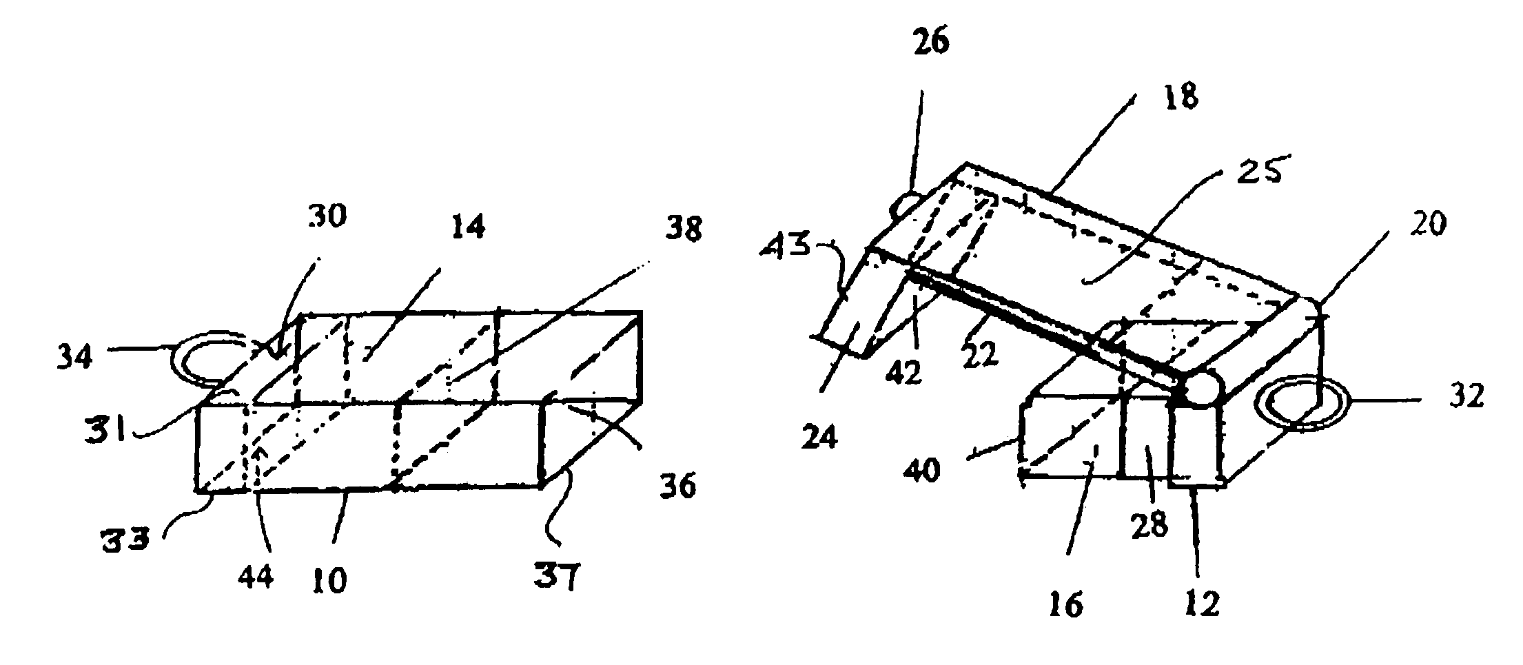
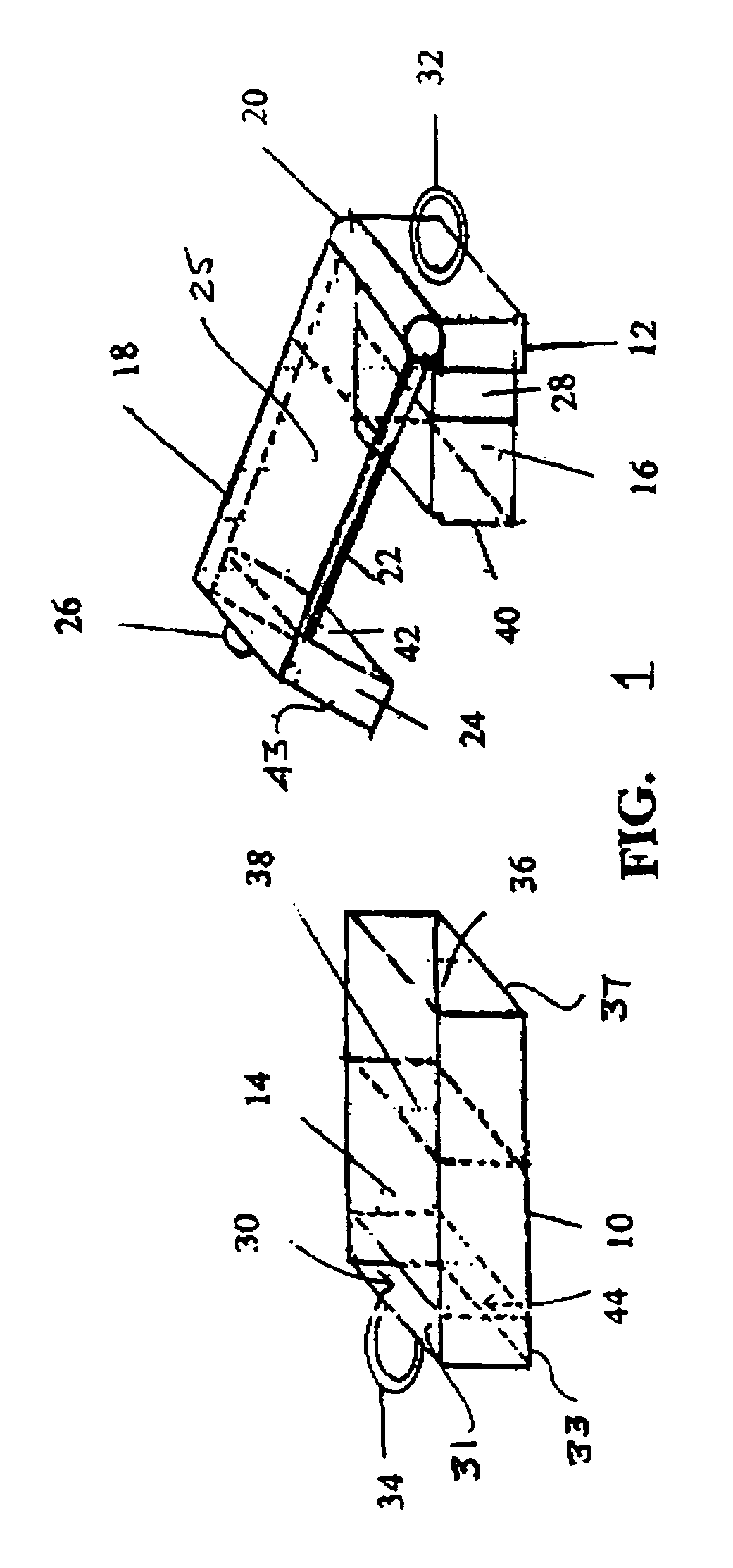
[0026]Referring now to FIG. 1, there is shown an exploded view of a magnetic jewelry clasp that is comprised of two housings 10, 12 that are adapted to be joined together to make up the jewelry clasp of the present invention. The housings 10, 12 can be made of many materials, preferable of the metal material, such as silver or gold that is the same as the material used in the piece of jewelry on which the clasp is being used.

[0027]As also can be seen, there is a magnetic means embedded or affixed within each of the housings 10, 12 and the magnetic means comprises permanent magnets 14, 16. The permanent magnets 14, 16 are arranged, spaced apart along a longitudinal line extending between the magnets and the polarity of each of the permanent magnets 14, 16 is predetermined as will also be explained.

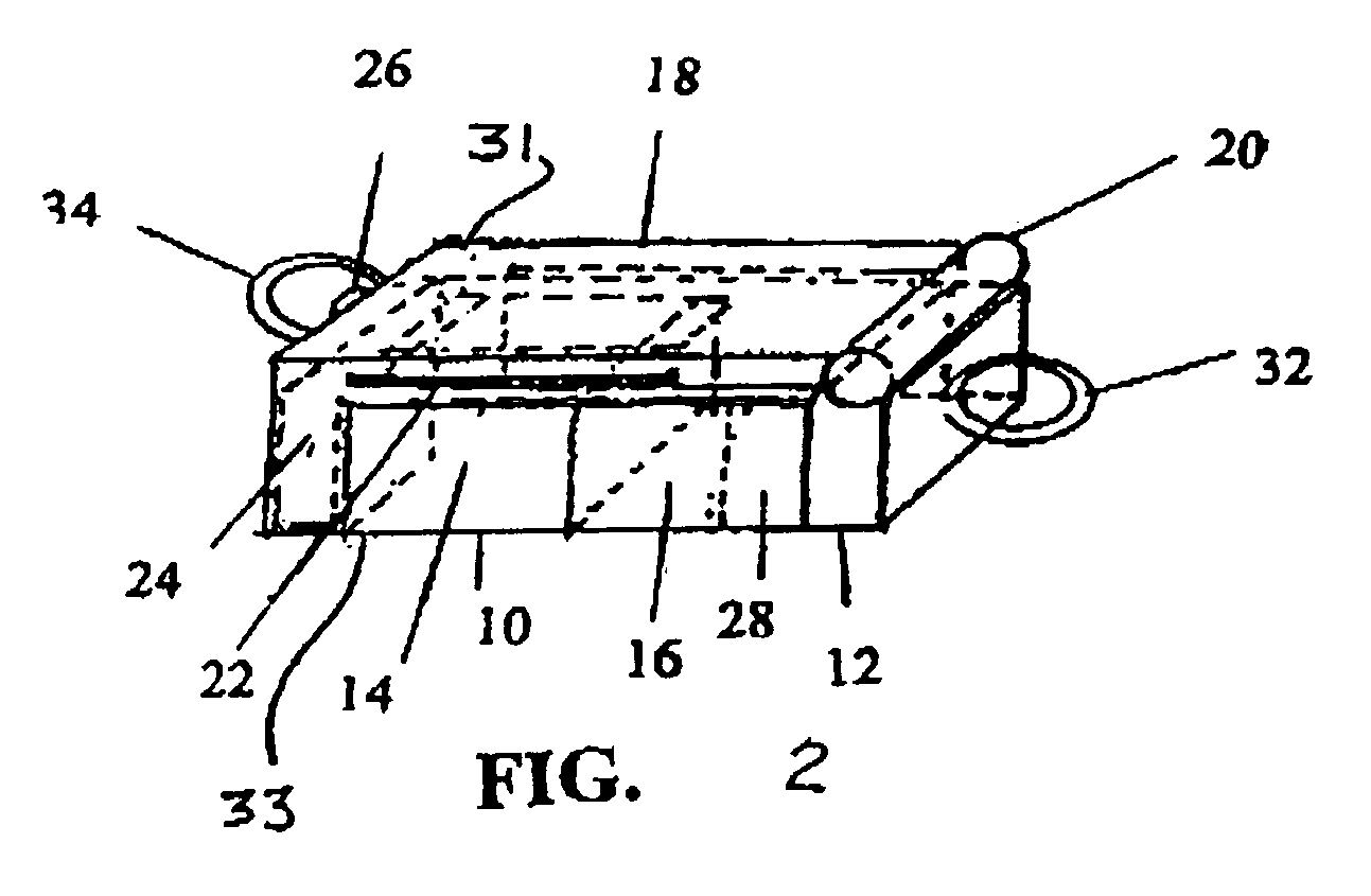
[0028]There is also a safety catch 18 that is pivotally affixed to the housing 12 by means of a hinge 20 so that the safety catch 18 is free to pivot about the hinge 20 between an open posi...


PUM


Abstract

A jewelry clasp having a pair of housings at the free ends of a piece of jewelry and are affixed together by magnetic forces. Each housing has a permanent magnet located therein and which magnets are attracted to each other when the housings are brought together. There is a safety catch on one of the housings having a protuberance extending therefrom that enters a slot in the other body. The slot passes entirely through the housing so that the protuberance can enter the slot in a first orientation and in a second orientation where one housing is inverted 180 degrees from the first orientation. The safety catch also includes a nib that aligns with an indentation formed in the slot and the entering of the nib into the indentation can be felt and/or heard by the wearer to provide assurance that the safety catch is in its locked position.

Description

REFERENCE TO RELATED CASES[0001]The present application is based upon and hereby claims priority to U.S. Provisional Application Ser. No. 60 / 448,027 filed Feb. 18, 2003 and entitled MAGNETIC JEWELRY CLASP.BACKGROUND OF THE INVENTION[0002]The present invention relates to jewelry and, more particularly, to an improved clasp for joining the two free ends of a jewelry chain together easily to facilitate that junction.[0003]With certain jewelry, particularly women's jewelry, there is an inherent conflict between the need to make the clasp easy to facilitate so that the wearer can readily join the free ends of the bracelet or necklace, and the need to make the clasp very secure so that it does not easily and inadvertently become unattached and risk the potential loss of the jewelry.[0004]Thus, even young people, having a great deal of dexterity, find it difficult to fasten necklaces behind their necks or fasten most bracelets which, by their nature, must be fastened with the use of only o...

Claims


Application Information

Patent Timeline
IPC IPC(8): A44C17/02A44C5/00
CPCA44C5/2042A44C5/2076Y10T24/32Y10S63/90A44D2203/00
Inventor FUHRMAN, ESTHER C.FUHRMAN, ROBERT J.
Owner EF DESIGNS
Why Eureka
Try Eureka