Metal support base

a support base and metal technology, applied in the field of support bases, can solve the problems of aging, affecting the safety and security of the articles and those surrounding, and the collapse of the support base, and achieve the effect of convenient laying of a large quantity of support bases, easy and organized manner

Inactive Publication Date: 2008-02-26
LIH YANN INDAL
View PDF4 Cites 21 Cited by
  • Summary
  • Abstract
  • Description
  • Claims
  • Application Information

AI Technical Summary

Benefits of technology

[0006]Thus, the present invention is aimed to provide a support base that is made of metal castings so as to be of heavy duty for carrying heavy articles without damage or breaking.
[0007]The present invention also provides a metal support base that allows expansion in longitudinal and lateral directions in an easy and organized manner so as to facilitate laying of a large quantity of support bases to cover an expanded area.
[0008]To realize the above objectives, in accordance with the present invention, there is provided a support base made of metal by die casting for supporting heavy articles above for example ground or floor, and comprising a rectangular flat grid plate having four corners from which pillar extend. Intermediate pillars extend from middle positions of long edge faces of the rectangle and a center pillar extends from a center of the rectangle. The rectangular grid plate has opposite end edges on which tenons and mortises are formed respectively and opposite side edges on which tenons and mortises are formed respectively so that a plurality of support bases can be connected together by the tenon-and-mortise coupling between adjacent support bases to expand a covering area of the support bases.

Problems solved by technology

For heavy articles, the support base is often collapsed, and even broken, or ages, for a long term use.
This adversely affects safety and security of the articles and those of the surrounding in which the articles are stocked.
Further, moving and organizing the conventional support base is very time-consuming and labor-consuming and is often subject to the space limitation of the surrounding where the articles are to be stocked.

Method used


Image

  • Metal support base
  • Metal support base
  • Metal support base

Examples


Embodiment Construction

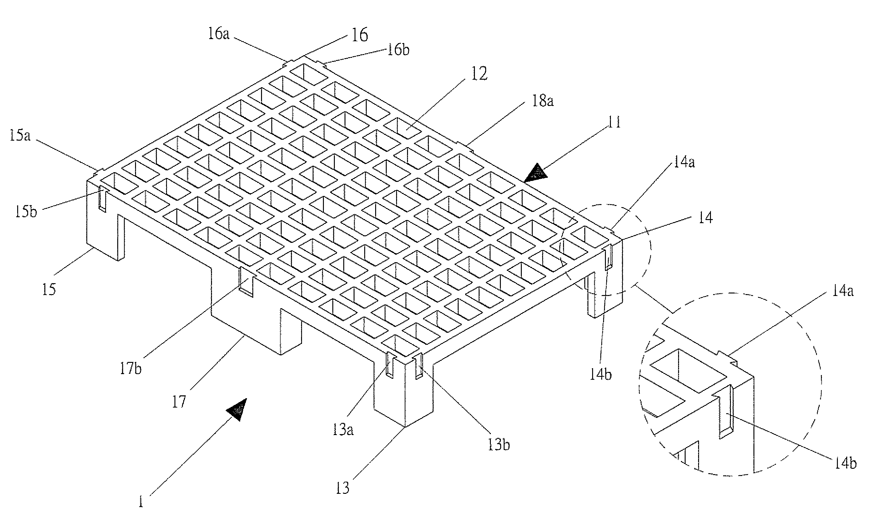
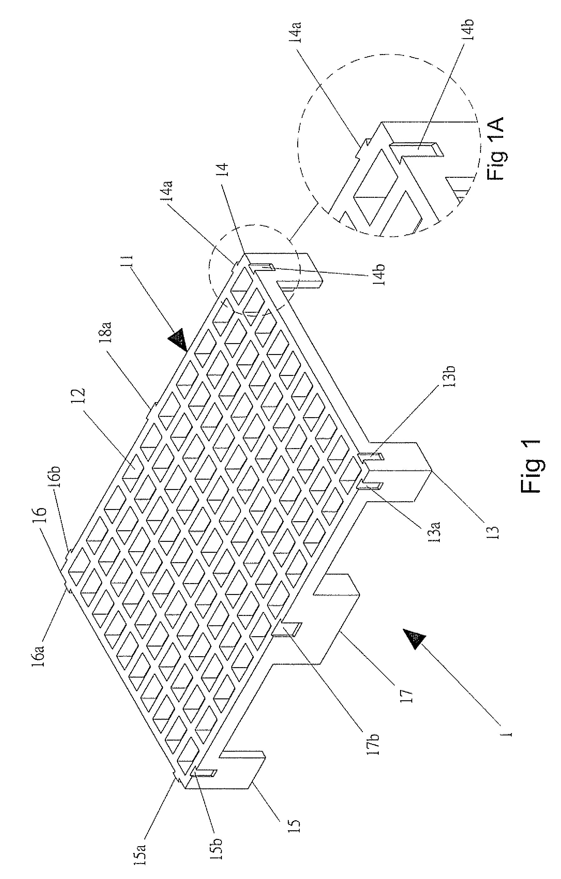
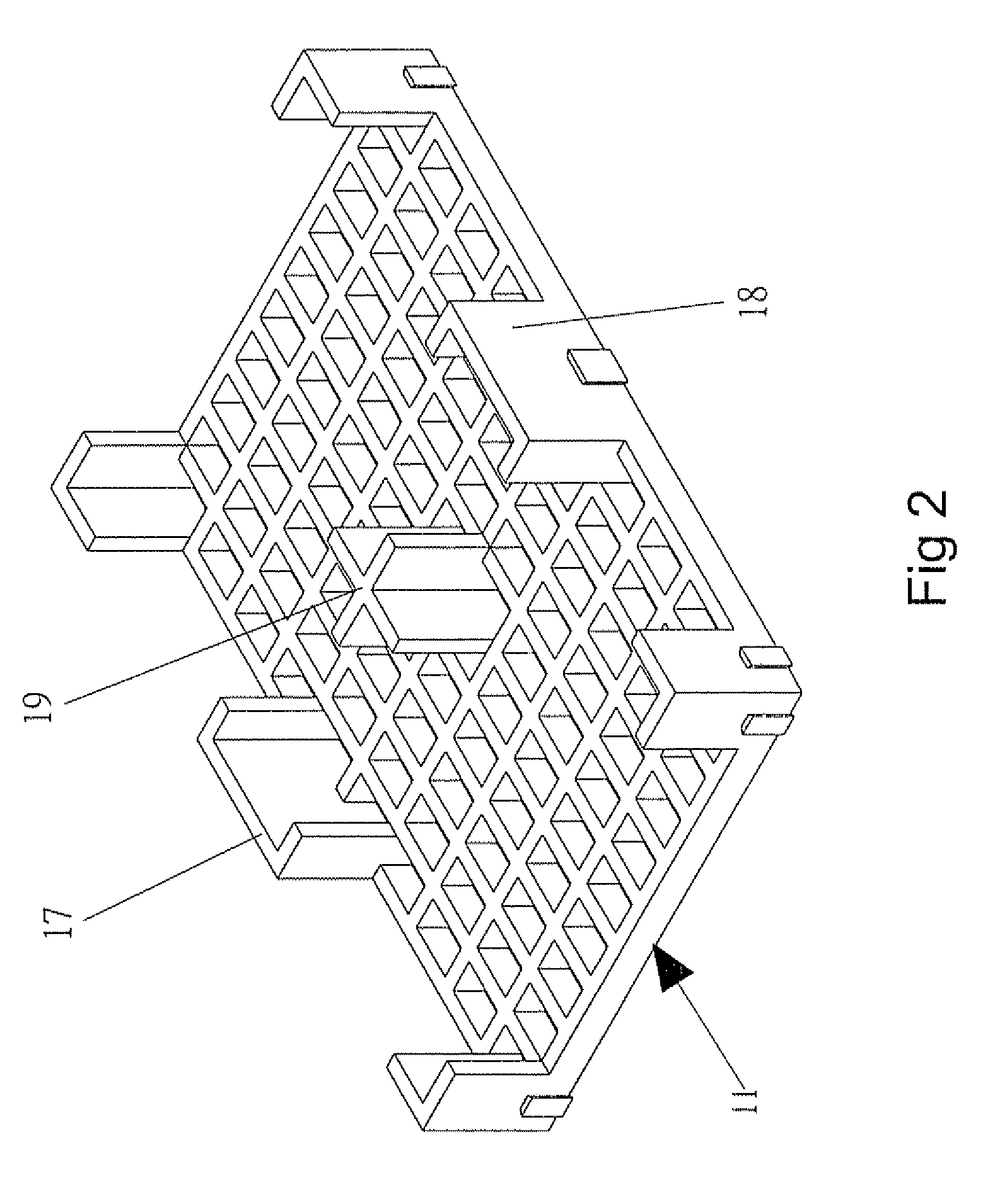
[0018]With reference to the drawings and in particular to FIGS. 1, 1A, and 2, a support base constructed in accordance with the present invention, generally designated with reference numeral 1, is made of a rigid and strong material by known means, such as die castings of metal. The support base 1 has a flat body 11 in the form of a rectangular grid plate comprising a plurality of longitudinally extending ribs and laterally extending ribs intersecting each other and defining hollow cells 12. Thus, the body 11 has two opposite end edges that extend in the lateral directions and are spaced from each other in the longitudinal direction and two opposite side edges that extend in the longitudinal direction and are spaced from each other in the lateral direction whereby the end edges and the side edges intersect each other at four corners, which are right-angled in the embodiment illustrated, but do not need to be so.

[0019]Pillars 13, 14, 15, 16 extend downward from the four corners respe...


PUM


Abstract

A support base is made of metal by die casting for supporting heavy articles above for example ground or floor, and includes a rectangular flat grid plate having four corners from which pillars extend. Intermediate pillars extend from middle positions of long edge faces of the rectangle and a center pillar extends from a center of the rectangle. The rectangular grid plate has opposite end edges on which tenons and mortises are formed respectively and opposite side edges on which tenons and mortises are formed respectively so that a plurality of support bases can be connected together by the tenon-and-mortise coupling between adjacent support bases to expand a covering area of the support bases.

Description

BACKGROUND OF THE INVENTION[0001]1. Field of the Invention[0002]The present invention relates generally to a support base that has a flat structure having a large surface area for being laid on for example floor to support and isolate an article thereon from humidity of the floor surface or ground, and in particular to such a support base made of metal for supporting heavy articles thereon.[0003]2. The Related Art[0004]Machinery and / or large quantity of articles are commonly positioned on for example floor or ground and often a support base, such as pallets, timbers, and thick paper boards, is positioned below the machinery or the articles to isolate the articles from contacting contaminants or humidity on the floor or ground. For heavy articles, the support base is often collapsed, and even broken, or ages, for a long term use. This adversely affects safety and security of the articles and those of the surrounding in which the articles are stocked. Further, moving and organizing th...

Claims


Application Information

Patent Timeline
Patent Type & Authority Patents(United States)
IPC IPC(8): B65D19/00
CPCB65D19/0018B65D21/0204B65D2519/00024B65D2519/00059B65D2519/00268B65D2519/00308B65D2519/00318B65D2519/00338B65D2519/00746
Inventor LIAO, LIN PO
Owner LIH YANN INDAL
Why Eureka
Try Eureka