Multi cyclone dust-collecting apparatus

a dust collection and multi-cyclone technology, applied in the direction of vortex flow apparatus, filtration separation, separation process, etc., can solve the problems of increasing the cost of manufacturing a multi-cyclone vacuum cleaner, multiple cyclones, etc., and achieve the effect of reducing or decreasing the number of elements and improving manufacturability

Inactive Publication Date: 2008-02-26
SAMSUNG GWANGJU ELECTRONICS CO LTD
View PDF14 Cites 63 Cited by
  • Summary
  • Abstract
  • Description
  • Claims
  • Application Information

AI Technical Summary

Benefits of technology

[0005]The present invention solves the above-mentioned problems of multi-cyclone vacuum cleaners by providing a multi cyclone dust-collecting apparatus having a reduced or decreased number of elements. Another aspect of the present invention is to provide a multi cyclone dust-collecting apparatus having improved manufacturability.

Problems solved by technology

An obvious problem with multi cyclone dust-collecting devices is that they have multiple cyclones.
Many parts are required in a multi-cyclone vacuum cleaner compared to a single cyclone dust-collecting apparatus, in addition to the additional piping required to connect each cyclone and to provide a discharge path each cyclone, increasing the cost to manufacture a multi-cyclone vacuum cleaner.

Method used


Image

  • Multi cyclone dust-collecting apparatus
  • Multi cyclone dust-collecting apparatus
  • Multi cyclone dust-collecting apparatus

Examples


Embodiment Construction

[0019]In the following description, same drawing reference numerals are used for the same elements even in different drawings. Well-known functions or constructions are not described in detail since they would tend to obscure the invention in unnecessary detail.

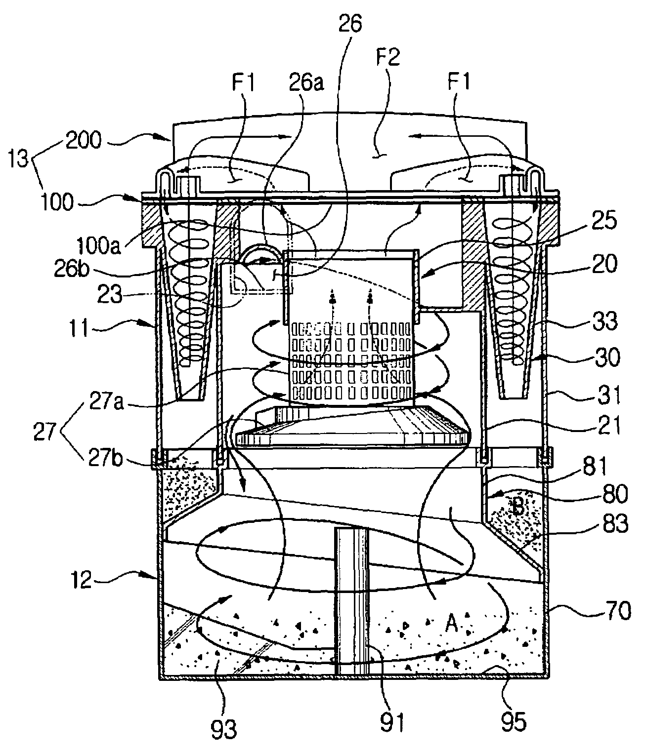
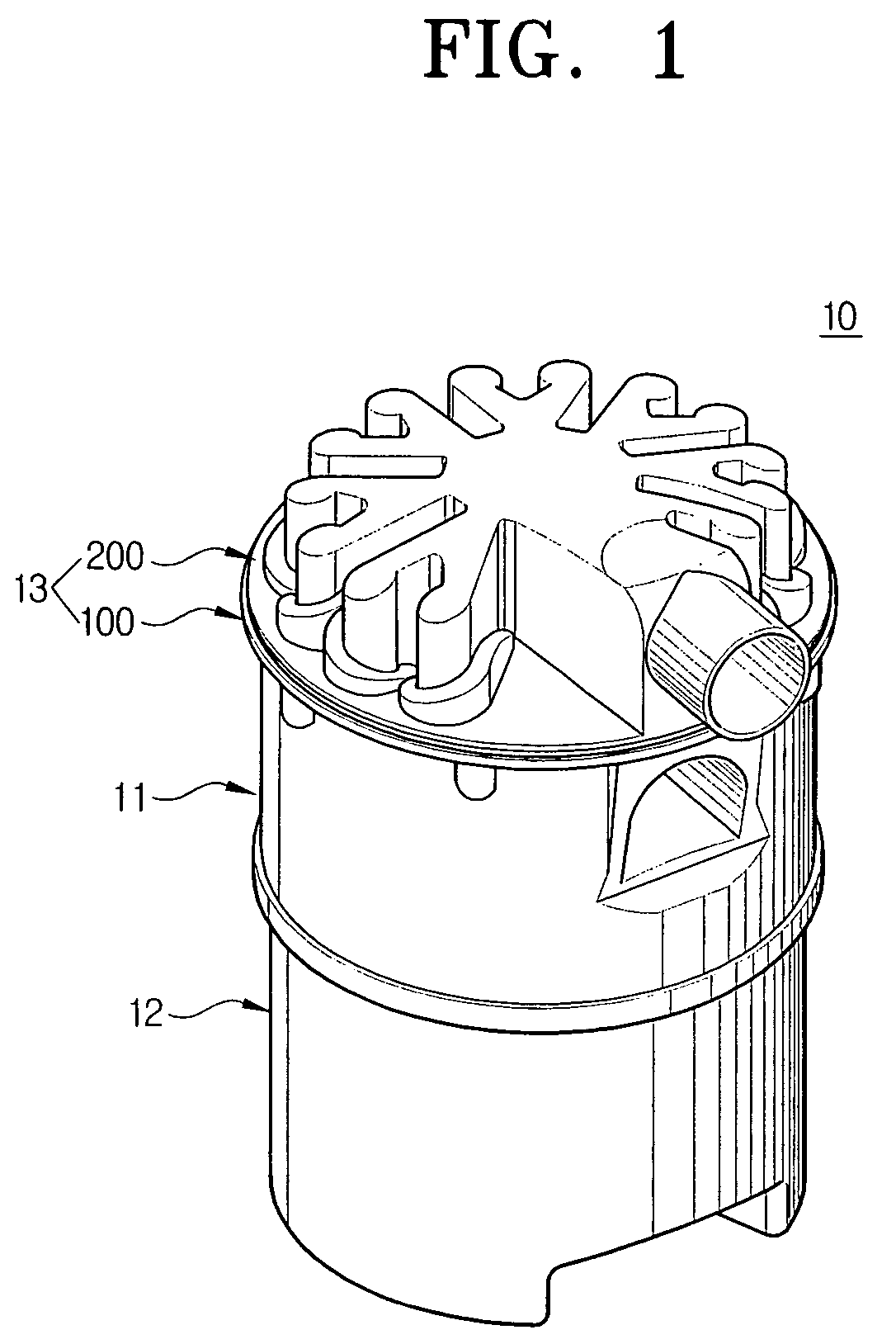
[0020]Referring to FIG. 1, a multi cyclone dust-collecting apparatus 10 comprises a multi cyclone chamber or unit 11, a contaminants collecting chamber unit 12 and a cover 13.

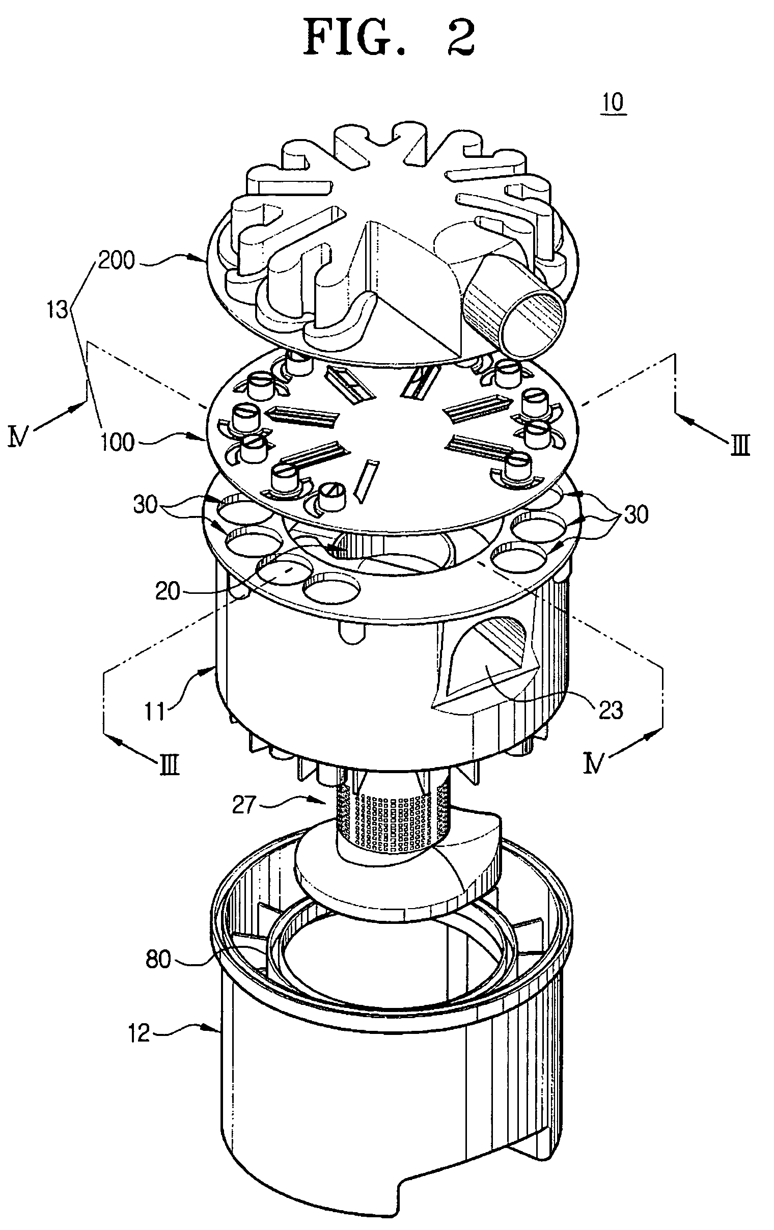
[0021]Referring to FIGS. 2 to 4, the multi cyclone unit 11 comprises a first cyclone 20 that separates relatively large air-borne particles and multiple secondary cyclones 30 that receive air from the first cyclone 20 and which thereafter separate smaller air-borne particles.

[0022]As shown in FIG. 3 and FIG. 4, the first cyclone 20 comprises a cylindrical inner case 21. As shown in FIG. 1, the cyclone also has a suction port 23 for drawing air into the inner case 21 and a grill member 27 that separates or screens large particles and which is connected to...


PUM

PropertyMeasurementUnit
areaaaaaaaaaaa
circumferenceaaaaaaaaaa
centrifugal forceaaaaaaaaaa

Abstract

A multi cyclone dust collecting apparatus comprises a multi cyclone unit having a first cyclone and a plurality of secondary cyclones. The first cyclone separates relatively large particles whereas the secondary cyclones separate out smaller particles. The cyclones are under a top cover mounted on a top portion of the multi cyclone unit and having a plurality of connecting covers forming a connecting path for guiding air flowing out of the first cyclone to the secondary cyclone, and a discharge cover forming a discharge path for guiding air flowing out of the secondary cyclone to the outside. The connecting covers and the discharge cover are integrally formed. A contaminant collecting unit is mounted to a bottom portion of the multi cyclone unit and collects contaminants separated from the first cyclone and the secondary cyclones.

Description

CROSS-REFERENCE TO RELATED APPLICATIONS[0001]This application claims the benefit of Korean Patent Application No. 2004-97265 filed on Nov. 25, 2004, in the Korean Intellectual Property Office, the disclosure of which is incorporated herein by reference in its entirety.FIELD OF THE INVENTION[0002]The present invention relates to a cyclone dust-collecting apparatus. More particularly, the present invention relates to a multi-cyclone dust-collecting apparatus, which centrifugally separates contaminants from air and centrifugally re-separates remaining small contaminants.BACKGROUND OF THE INVENTION[0003]In general, a cyclone vacuum cleaner separates contaminants from dirt-laden air using centrifugal force. Recently, so-called multi-cyclone dust-collecting devices have been developed wherein two or more cyclones are arranged in series or parallel to improve dust separating / collecting efficiency.[0004]An obvious problem with multi cyclone dust-collecting devices is that they have multiple...

Claims


Application Information

Patent Timeline
Patent Type & Authority Patents(United States)
IPC IPC(8): B01D45/12A47L9/16B04C5/185B04C5/24
CPCA47L9/1625A47L9/1641B04C5/12B04C5/185B04C5/26B04C5/28A47L9/16B04C5/24B01D45/12
Inventor OH, JANG-KEUN
Owner SAMSUNG GWANGJU ELECTRONICS CO LTD
Why Eureka
Try Eureka