Wall element for magnetically shielded room and magnetically shielded room

a wall element and magnetic shielding technology, applied in the field of wall elements, can solve the problems of limited active compensation degree, induced field counterbalancing, limited active shielding efficiency, etc., and achieve the effect of improving shielding, boosting shielding, and strengthening the “-aluminum”

Active Publication Date: 2008-02-26
ELEKTA NEUROMAG
View PDF6 Cites 13 Cited by
  • Summary
  • Abstract
  • Description
  • Claims
  • Application Information

AI Technical Summary

Benefits of technology

[0030]According to the invention, the layers are mounted in an alternating order one upon the other in surface contact with each other without any separating air gaps, so that each first layer having a high electrical conductivity lies between each second and third layers having a high permeability substantially in surface contact with the second and third layers, said layers together forming a compact structure in which the product (σ×μ) of electrical conductivity (σ) and permeability (μ) is maximized so as to minimize the penetration depth of magnetic interference.
[0067]The preassembly of these elements at the factory can be automated. This minimizes the handling of the separate thin ferromagnetic plates and prevents the reduction of their permeability, which would result from harsh mechanical handling. In the finished element, the aluminum plate between two ferromagnetic ones extends further out and protects them during further handling and assembly of the magnetically shielded room.

Problems solved by technology

The efficiency of active shielding is, however, limited by the performance of the control system.
Even if this geometric performance of the system were sufficient, the degree of active compensation is always limited by the intrinsic noise level and operation band of the flux meters producing the difference signal.
A high-permeability material shields the surrounding space by getting strongly magnetized, which leads to the appearance of an induced field counterbalancing the magnetizing interference field in the vicinity of the magnetized material.
The conductivity being finite leads to damping of the induced currents so that this mechanism contributes to shielding only at higher frequencies and is totally ineffective in the case of a static field.
This way of thinking has led to very large and heavy magnetically shielded room designs, especially because in a biomagnetic application the space requirement inside the innermost shell is already about 3*4*2.5 m3.
Such a multi-shell magnetically shielded room may weigh about ten tons and can only be installed in a two-floor space because it has a height of 3.5 m. It is expensive and requires, a complicated door construction; a slow-to-operate multiple door arrangement may be necessary when more than two shells are used.
These are the principal disadvantages of prior-art solutions.
Increasing the wall thickness would of course be a brute-force method of reducing the threshold frequencies, but it would lead to expensive and heavy structures.

Method used


Image

  • Wall element for magnetically shielded room and magnetically shielded room
  • Wall element for magnetically shielded room and magnetically shielded room
  • Wall element for magnetically shielded room and magnetically shielded room

Examples


Embodiment Construction

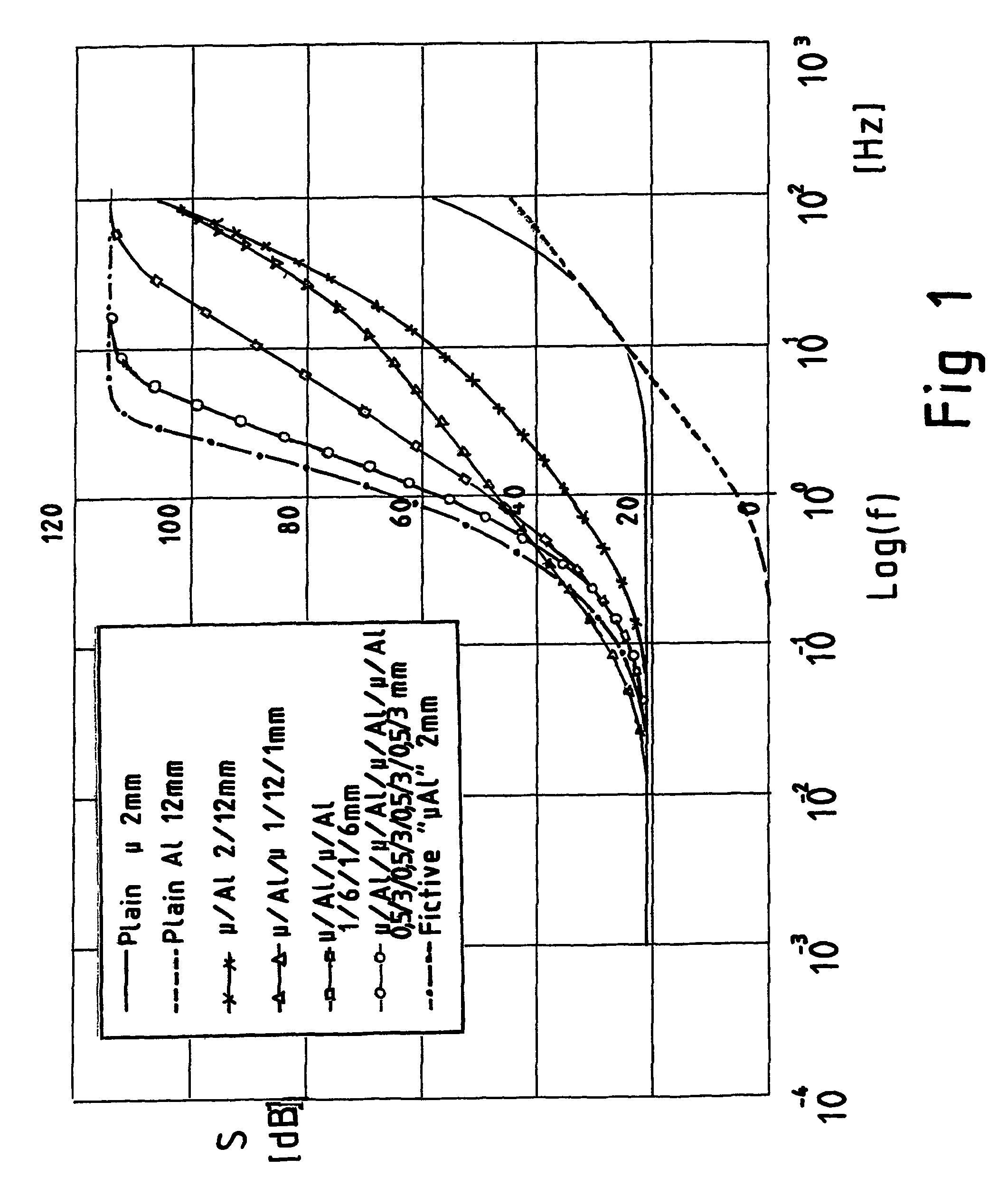
[0073]The composite magnetic shield according to the present invention works as indicated in FIG. 1 only if the magnetic and electric continuity is taken care of in each wall of the sandwich structure and in each one of its subshells. Assembling the wall elements from a very large number of separate sheets is laborious, and the thickness tolerances tend to prevent achieving the required electric and magnetic contact in the joints between the elements. For this reason, the extreme sandwich structure—made up of a very large number of thin metal sheets, and having the best shielding properties—is rather impractical.

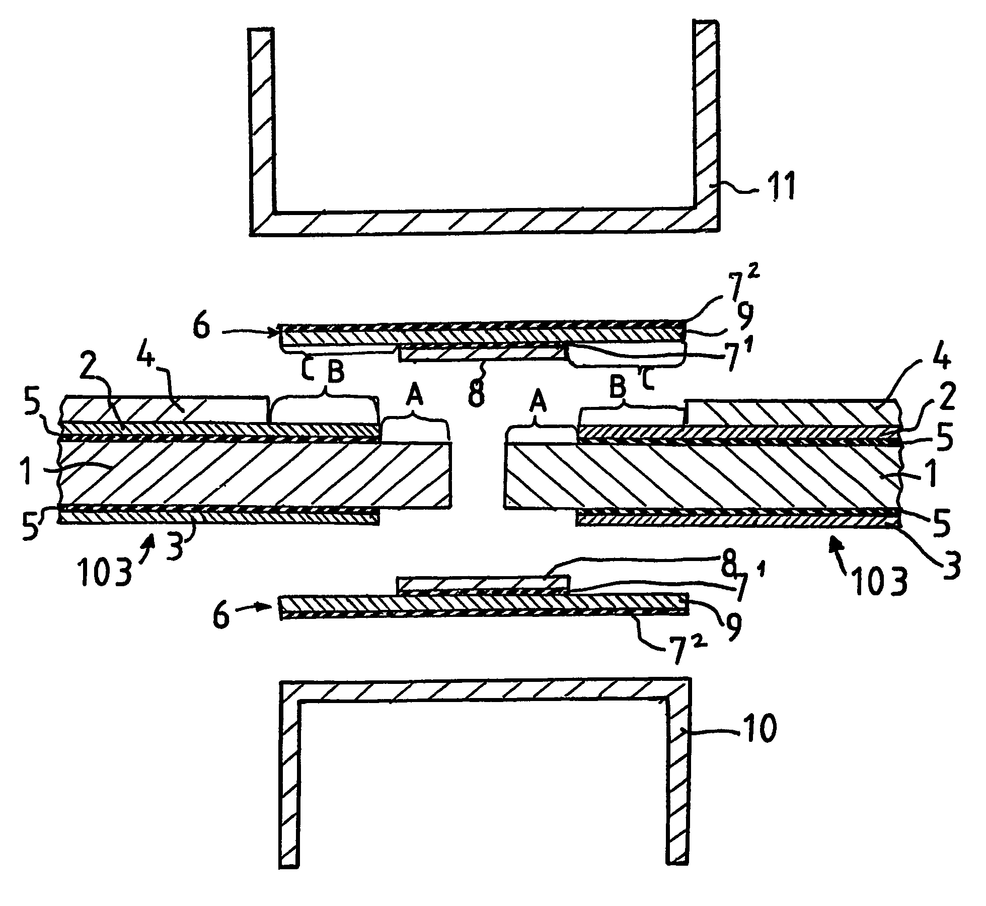
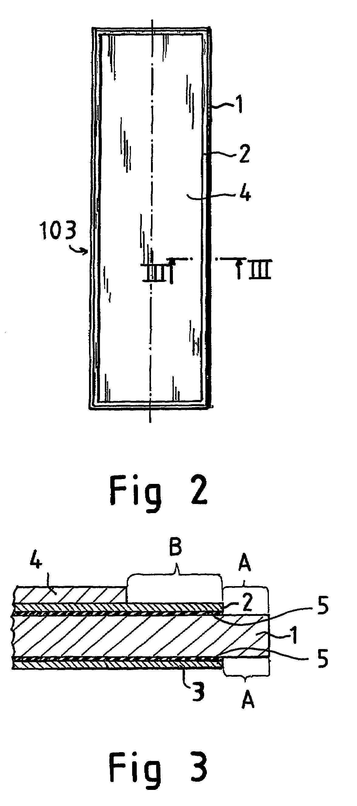
[0074]Therefore, a simple four layer element as presented in FIGS. 2 and 3 is described by way of example as a preferred embodiment.

[0075]Referring to FIGS. 2 and 3, the wall element 103 consists of four rectangular metal plates mounted face-to-face by gluing or mechanically. The element comprises a first layer 1, which is a sheet of highly conductive metal, e.g. aluminum (A...


PUM


Abstract

The invention relates to a wall element for a magnetically shielded room and to a magnetically shielded room. The wall element comprises at least one first layer (1) which is formed of metal plate having a high electrical conductivity, and at least two layers, a second layer (2) and a third layer (3), which consist of metal plates having a high magnetic permeability. The layers (1, 2, 3) are superimposed one on top of another in surface contact with each other without any separating air gaps, so that each first layer (1) having a high electrical conductivity lies between each second (2) and third layers (3) having a high permeability substantially in surface contact with the second and third layers, the layers together forming a compact structure in which the product (σ×μ) of electrical conductivity (σ) and permeability (μ) is maximized so as to minimize the penetration depth of magnetic interference.

Description

FIELD OF THE INVENTION[0001]The present invention concerns a wall element as defined in the preamble of claim 1. Moreover, the invention concerns a magnetically shielded room as defined in the preamble of claim 16.[0002]The present invention relates to shielding of sensitive devices against magnetic interference occurring in their environment. Examples of devices requiring electromagnetic shielding specifically against magnetic fields are ultrasensitive measuring devices like SQUID-based magnetometers used in biomagnetism, or electron beam lithography devices used for making patterns on nano-scale thin films in semiconductor industry. These devices are typically operated in urban areas close to sources of strong magnetic interference such as trains and cars—which cause interference predominantly in the low frequency domain below one Herz—and digital electronic equipment and computers emitting radiation at higher frequencies up to the megaherz range.DESCRIPTION OF PRIOR ART[0003]The ...

Claims


Application Information

Patent Timeline
Patent Type & Authority Patents(United States)
IPC IPC(8): H05K9/00E04B1/92G01R33/02
CPCH05K9/0001H05K9/0003
Inventor SIMOLA, JUHA
Owner ELEKTA NEUROMAG
Why Eureka
Try Eureka