Image display system

a display system and image technology, applied in the field of image display systems, can solve the problems of not being able to see an image, affecting the image quality of the image,

Active Publication Date: 2008-02-26
ASAHI GLASS CO LTD
View PDF20 Cites 137 Cited by
  • Summary
  • Abstract
  • Description
  • Claims
  • Application Information

AI Technical Summary

Benefits of technology

[0010]It is an object of the present invention to provide a novel and unique technique capable of preventing a screen per se from being unpleasant to the eye, giving almost no feeling of oppression to a viewer and giving a feeling of expansion to the viewer when the screen is not active, and capable of displaying an image having a feeling of transparency when the screen is active, whereby the viewer can see an image on the screen and a scene behind the screen.
[0011]It is another object of the present invention to provide a novel and unique technique capable of realizing a state wherein a viewer can have an impression that a transparent image looks like floating in the air or of displaying a three-dimensional image having a feeling of depth.
[0024]In accordance with the present invention, when the image display system is not active, the screen can turn transparent to be prevented itself from being unpleasant to the eye, minimize a feeling of oppression to a viewer and give a feeling of expansion to the viewer. When the image display system is active, the screen can display an image having a feeling of transparency, whereby the viewer can simultaneously see an image on the screen and a scene behind the screen.
[0025]Additionally, the image display system can realize a state wherein the viewer can have an impression that a transparent image looks like floating in the air.

Problems solved by technology

However, since the display portions per se are not transparent, the display portions per se are unpleasant to the eye or give a feeling of oppression to a viewer when the display portions are active and even when the display portions are not active.
In this method, since the half-mirror or the hologram system is not completely transparent when no image is displayed, the half-mirror or the hologram system is visible and unpleasant to the eye.
However, when a viewer is located at an oblique position to the screen, the viewer cannot see an image since this system has a narrow viewing angle because of a viewing angle dependency.
This system can not realize a state with an image displayed in a background scene since the screen is not transparent while displaying the image.
When the image is displayed, it is not possible to see a scene behind the image.

Method used


Image

  • Image display system
  • Image display system
  • Image display system

Examples


example 1

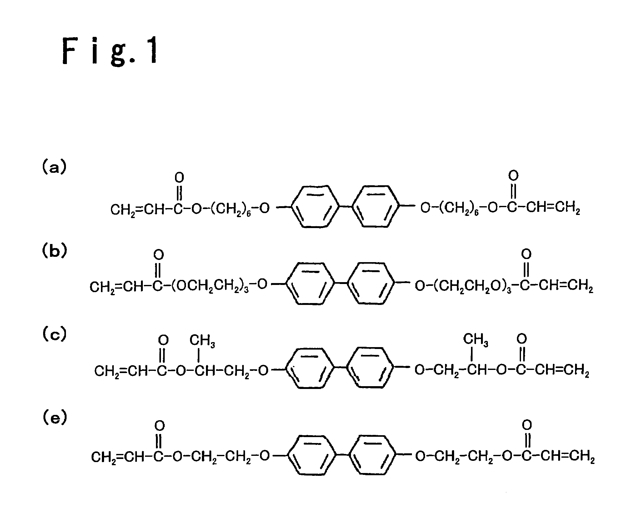
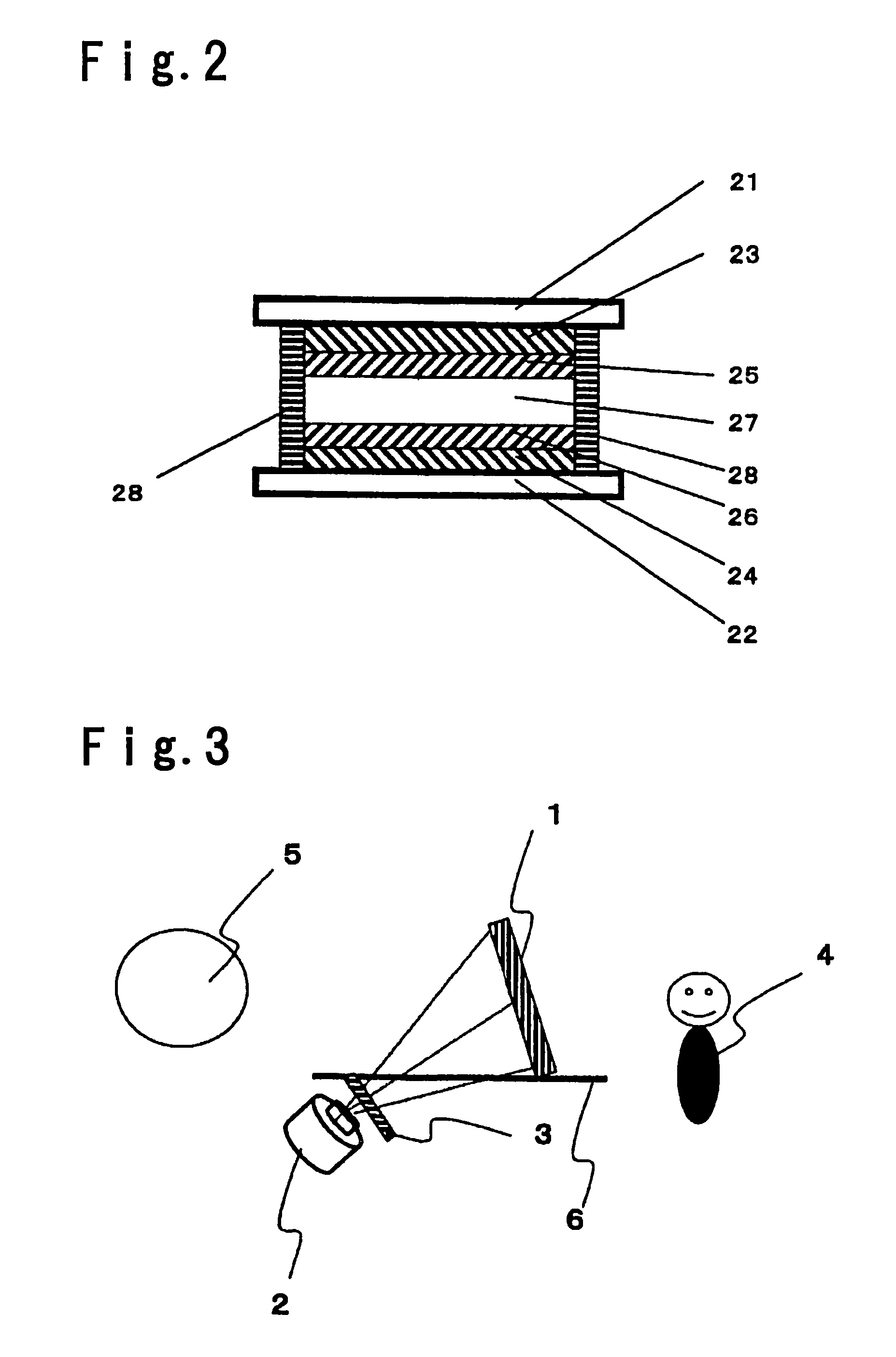
[0144]A screen, which has a cross-sectional shape schematically shown in FIG. 2, was fabricated as follows: First, 80 parts of a nematic liquid crystal having a negative dielectric anisotropy (AG-1016XX, manufactured by Chisso Corporation), 20 parts of a curable compound represented by the formula (a) in FIG. 1, and 0.2 part of benzoin isopropyl ether were blended to prepare a mixed composition.

[0145]Next, a pair of glass substrates, which had polyimide films for vertical alignment (JALS-682-R3, manufactured by JSR Corporation) formed on transparent electrodes and had a length of 200 mm, a width of 200 mm and a thickness of 1.1 mm, were provided so that the polyimide films faced each other. After a very small amount of resin beads having a diameter of 6 μm were sprayed in the gap between the polyimide films, the substrates were bonded by an epoxy resin printed in a width of about 1 mm along the four sides of a substrate, and the epoxy resin was cured. Thus, the screen was prepared s...

example 2

[0154]Two screens, each of which was fabricated in the same way as Example 1, were provided as shown in FIG. 5. The screen 1 and the screen 1′ were provided parallel with each other, having a gap of about 50 mm therebetween. From the position of a viewer, the two screens looked like being provided in a substantially overlapping fashion.

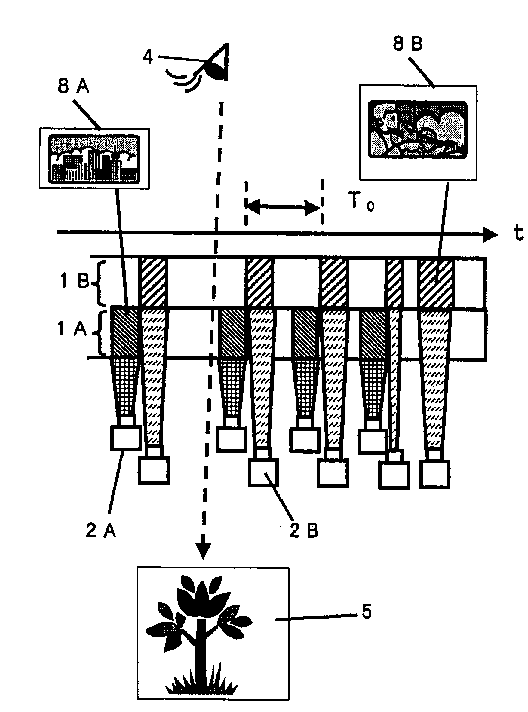
[0155]With respect to the image-projecting unit, two image-projecting units, each of which was the same model as Example 1, were used. With respect to the shutter, two mechanical rotary choppers, each of which was the same model as Example 1, were used and were controlled so as to be operated on the projection timing as shown in FIG. 6. The time periods T11, T12, T21, T22, T1 and T2 were set at T11=4 ms, T12=12 ms, T21=4 ms, T22=12 ms, T1=8 ms and T2=8 ms, respectively.

[0156]An image was displayed on the screen 1 by an image-projecting unit 2, and a character image was displayed on the screen 1′ by the other image-projecting unit 2′. In the image disp...

example 3

[0164]A screen was fabricated in the same way as Example 1 except that the surfaces of the polyimide films for vertical alignment were subjected to rubbing, and the pretilt angle was set at an angle of 70 deg.

[0165]In the driving operation wherein the liquid crystal layer of the screen changed between the light transmissive state and the light scattering state, the rise time was about 1.0 ms, and the fall time was about 1.5 ms.

[0166]The screen 1, the image-projecting unit 2 and the shutter 3 were provided with respect to a viewer 4 in the arrangement shown in FIG. 3. By the image display system in this example, the viewer 4 was able to simultaneously see an image on the screen and a scene 5 behind the screen, being free from flickering, as in Example 1. When a voltage was not applied, the system gave a feeling of expanse to the viewer since the screen completely exhibited the light transmissive state as in Example 1. When the image display system was active, the viewer had an impres...


PUM

PropertyMeasurementUnit
repetition frequencyaaaaaaaaaa
pretilt angleaaaaaaaaaa
distanceaaaaaaaaaa

Abstract

An image display system includes a screen comprising a pair of substrates with transparent electrodes provided thereon, and a liquid crystal layer sandwiched between the substrates, the liquid crystal layer containing a cured resin and being capable of exhibiting a light transmissive state and a light scattering state; and an image-projecting unit for projecting an image on the screen; wherein a frame comprising a combination of the light transmissive state and the light scattering state as a minimum repetitive satisfies a certain relationship.

Description

TECHNICAL FIELD[0001]The present invention relates to an image display system wherein a transparent member, such as a glass member, is used as a screen, and an image projected from a projector is displayed on the screen.BACKGROUND ART[0002]With respect to current image display systems, such as CRTs, PDPs and liquid crystal displays, attempts have been rapidly made to make the display portions thinner or flat.[0003]However, since the display portions per se are not transparent, the display portions per se are unpleasant to the eye or give a feeling of oppression to a viewer when the display portions are active and even when the display portions are not active. For these reasons, it has been demanded to provide a display portion, which can turn transparent so as to give a feeling of expansion to a viewer and allows the viewer to see a scene behind the display portion.[0004]As one of the solutions, there is, e.g., a display system called a head-up display for a car. This is a method wh...

Claims


Application Information

Patent Timeline
Patent Type & Authority Patents(United States)
IPC IPC(8): G09G5/00G02F1/1334G02F1/1347G02F1/137
CPCG02F1/1334G02F1/1375G02F1/13476H04N9/3155G02B27/02G02F1/13
Inventor OZEKI, MASAOISSHIKI, MASANOBUTAHARA, SHINYASUZUKI, TOSHIHIKO
Owner ASAHI GLASS CO LTD
Why Eureka
Try Eureka