Plug-in coupling for fluidic systems

a fluidic system and plug-in technology, applied in the direction of adjustment joints, pipe/joints/fittings, pipe-joints, etc., can solve the problem of separation again from the coupling par

Inactive Publication Date: 2008-03-04
VOSS AUTOMOTIVE
View PDF16 Cites 7 Cited by
  • Summary
  • Abstract
  • Description
  • Claims
  • Application Information

AI Technical Summary

Benefits of technology

[0004]The present invention is based on the object of providing an alternative, generic plug-in coupling which is suitable in parti...

Problems solved by technology

The disadvantage of a known plug-in coupling of this type is, if the housing is designed as a single part, firstly that the plug part, after being inserted int...

Method used


Image

  • Plug-in coupling for fluidic systems
  • Plug-in coupling for fluidic systems
  • Plug-in coupling for fluidic systems

Examples


Embodiment Construction

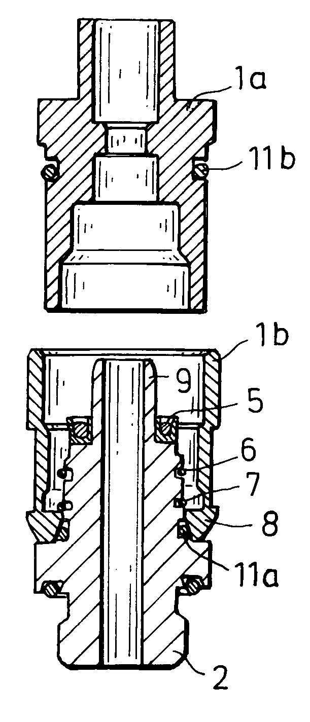
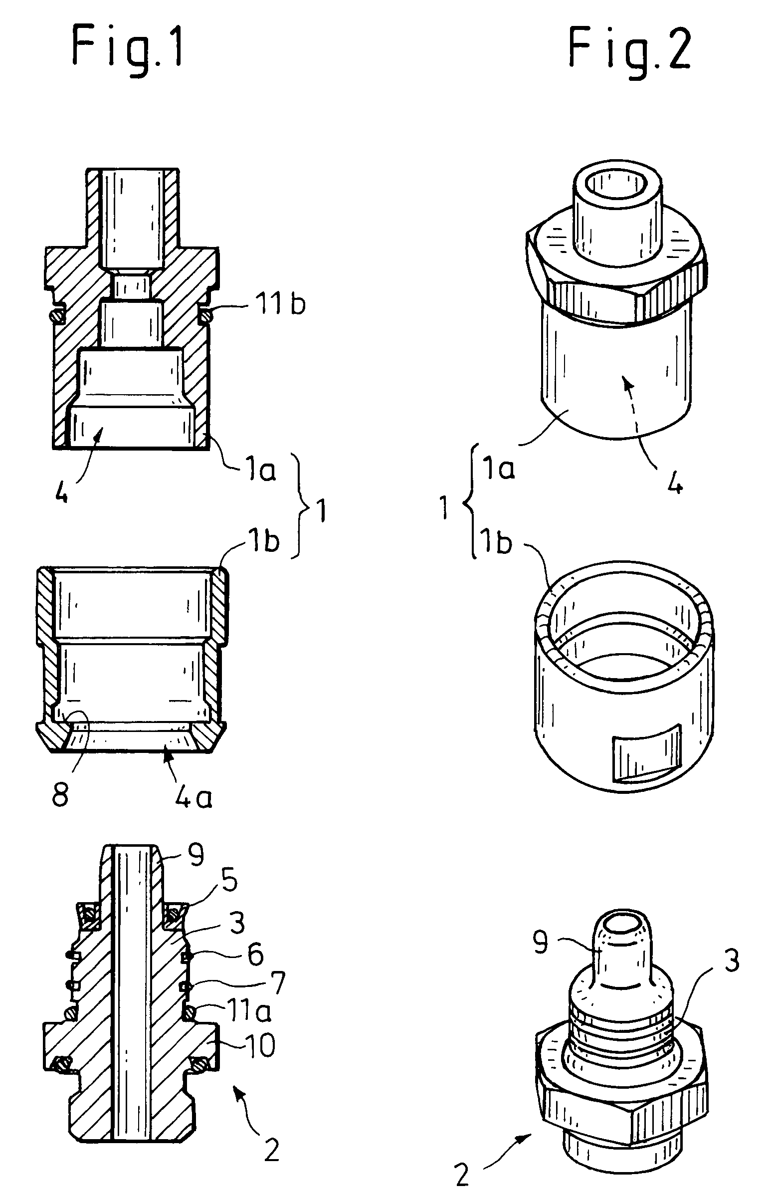
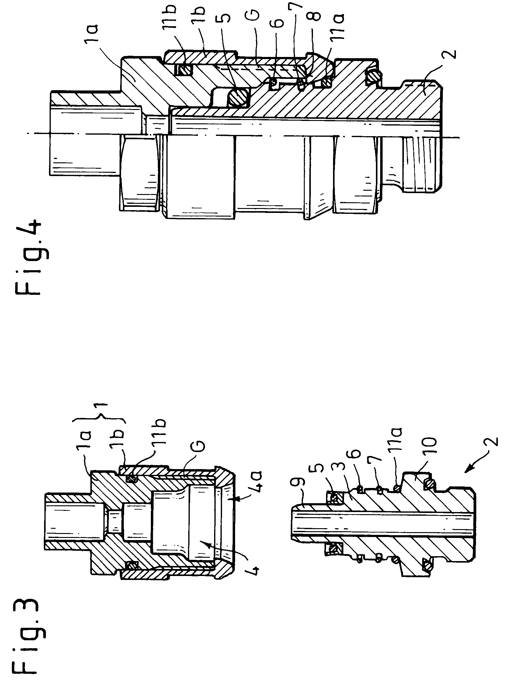
[0023]As emerges first of all from FIGS. 1 and 2, a plug-in coupling according to the invention for fluidic systems, in particular for CO2— and fuel-conducting systems, comprises a housing 1 and a plug 2 which can be inserted into the housing 1, it being possible for the plug 2 to be inserted by means of a plug stem 3 into a receiving opening 4 of the housing 1 in a manner sealed by at least one circumferential seal 5. The plug 2 can be locked against release when inserted in the receiving opening 4 by means of a locking device (not described more specifically in its entirety).

[0024]The locking device here comprises at least one latching element—two latching elements 6, 7 arranged axially one behind the other on the plug 2 in the design illustrated, and a latching shoulder 8 interacting in each case with a latching element 6, 7. The latching elements 6, 7 are formed in each case by a snap ring held in a respective annular groove (not described more specifically) of the plug 2.

[0025]...


PUM


Abstract

A plug-in coupling for fluidic systems, in particular for CO2— and fuel-conducting systems, including a housing (1) and a plug (2) which can be inserted into the housing (1). The plug (2) can be inserted by a plug stem (3) into a receiving opening (4) of the housing (1) in a manner sealed by at least one circumferential seal (5, 5a, 5b) and, when inserted, it can be locked therein against release by a locking device having at least one latching element (7) arranged on the plug (2) and a latching shoulder (8) interacting with the latching element (7). The housing (1) has two-part design with an inner housing part (1a) and an outer housing part (1b), which can be connected releasably to the inner housing part (1a) so that it essentially surrounds the inner housing part (1a). In order to install it without destroying it, the latching shoulder (8) is formed at one end in an entry region (4a) of the receiving opening (4) on the outer housing part (1b).

Description

BACKGROUND OF THE INVENTION[0001]The present invention relates to a plug-in coupling for fluidic systems, in particular for CO2— and fuel-conducting systems, comprising a housing and a plug which can be inserted into the housing, it being possible for the plug to be inserted by means of a plug stem into a receiving opening of the housing in a manner sealed by at least one seal and, when inserted, for it to be locked therein against release by means of a locking device comprising at least one latching element arranged on the plug and a latching shoulder interacting with the latching element, and the housing being of two-part design by comprising an inner housing part and an outer housing part, which can be connected releasably to the inner housing part and essentially surrounds the inner housing part.[0002]A plug-in coupling of this type is disclosed in EP 0 766 033 B1. In this document, a plug-in coupling for pneumatic pressure-medium systems, in particular, is described, said plug-...

Claims


Application Information

Patent Timeline
IPC IPC(8): F16L27/00F16L37/088
CPCF16L37/088F16L2201/10F16L2201/20
Inventor HOFFMANN, MARTIN
Owner VOSS AUTOMOTIVE
Why Eureka
Try Eureka