Method and device for the subjective determination of aberrations of higher order

a technology of higher order and aberration, applied in the field of higher order subjective determination, can solve the problems of inability to use adaptive lenses industrially, and inability to subjectively fine adjus

Inactive Publication Date: 2008-03-04
CARL ZEISS MEDITEC AG
View PDF6 Cites 16 Cited by
  • Summary
  • Abstract
  • Description
  • Claims
  • Application Information

AI Technical Summary

Benefits of technology

[0006]An object of the present invention is to provide a method and a device for the subjective determination o

Problems solved by technology

However, this objective improvement in quality displays differences from the subjectively evaluated visual power of this optical system.
However, a subj

Method used


Image

  • Method and device for the subjective determination of aberrations of higher order
  • Method and device for the subjective determination of aberrations of higher order
  • Method and device for the subjective determination of aberrations of higher order

Examples


Embodiment Construction

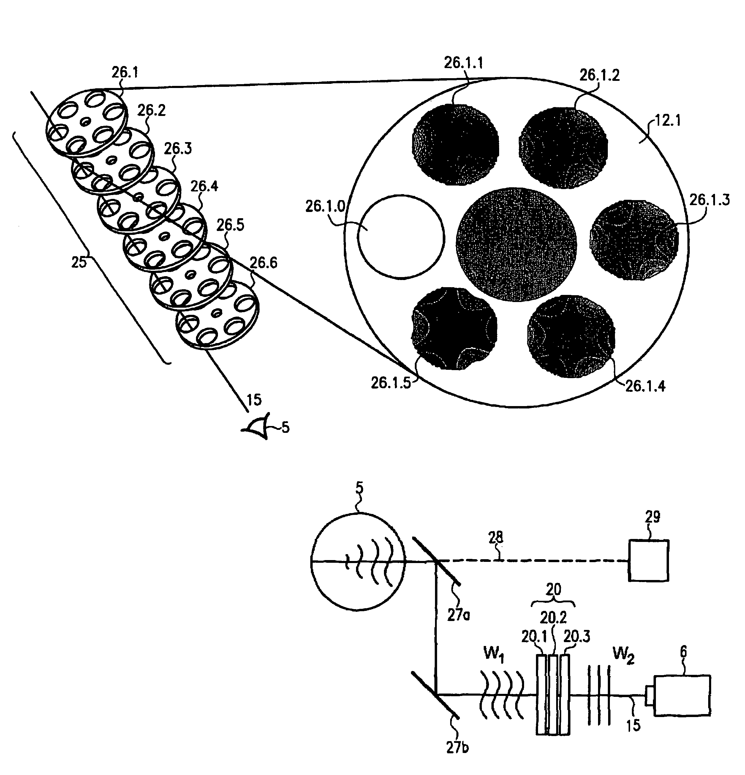
[0036]A plate set for 3rd-degree coma image errors of the x axis and 3rd-order spherical aberration, each with a subset for polynomial coefficients from 0.5 to 10, is schematically represented in FIG. 1. The plate set for 3rd-degree coma image errors in the x axis according to the formula W(p,θ)=(3p2−2p) sin(θ) is designated A and the sub-plate set for the image error of the 3rd-order spherical aberration according to the formula W(p,θ)=6p4−6p2+1 is designated B. These two subsets A and B together form the plate set according to FIG. 1. Subsets A and B each consist of five individual plates which are laid out within the defined Zernike polynomial for different polynomial coefficients, i.e. amplitudes. Thus subset A has individual plates for polynomial coefficients 0.5, 1.0, 2.5, 5 and 10. Subset B also consists of five plates with different polynomial coefficients 0.5, 1.0, 2.5, 5 and 10. With this plate set, consisting of subsets A and B, image errors can then be determined and com...


PUM


Abstract

A device for the subjective determination of aberrations of higher orders Xi in an optical system, in particular in an eye includes at least one observation channel into which defined plates can be introduced, the individual plates having optically active structures which correspond to a defined Zernike polynomial and to a defined amplitude, at least one order Xi of the Zemike polynomial being greater than two.

Description

BACKGROUND[0001]The present invention relates to a method and a device for the subjective determination of aberrations of higher order in an optical system, in particular in an eye.[0002]In order to improve the quality of optical systems such as imaging systems and laser irradiation, optical wavefronts of these systems are analysed. In the article “Objective measurement of wave alternations of the human eye with the use of a Hartmann-Shack wave front sensor” by Liang et al, Optical Society of America 1994, p. 1949 ff., it is described how, with Shack-Hartmann sensors, aberrations of higher order can be recorded and evaluated in the form of Zernike coefficients of the various orders.[0003]This objective determination of the Zernike coefficients results in an improvement in quality of the system. However, this objective improvement in quality displays differences from the subjectively evaluated visual power of this optical system.[0004]This fact has been taken into account for the con...

Claims


Application Information

Patent Timeline
IPC IPC(8): A61B3/00A61B3/04
CPCA61B3/028
Inventor DICK, MANFREDSCHROEDER, ECKHARDMAEUSEZAHL, HOLGER
Owner CARL ZEISS MEDITEC AG
Why Eureka
Try Eureka