Harness outlet structure of engine

a technology of harness outlet and engine, which is applied in the direction of insulated conductors, cables, conductors, etc., can solve the problems of inability to properly shield the wiring harness routed from these electric components, and the shielding becomes simply incomplete relative to the inside of the shield cover

Inactive Publication Date: 2008-03-04
HONDA MOTOR CO LTD
View PDF3 Cites 10 Cited by
  • Summary
  • Abstract
  • Description
  • Claims
  • Application Information

AI Technical Summary

Benefits of technology

[0007]It is an object of the present invention to solve the aforementioned problem of the prior art and provide a harness outlet structure of an engine that is capable of providing a reliable shield from electromagnetic waves at the harness outlet disposed between the engine and the edge portion of the shield cover.
[0013]The following effects can be achieved according to the present invention. Specifically:
[0014]In accordance with the first aspect of the present invention, the shield cover and the shield outer jacket body of the wiring harness are connected via the grommet bracket so as to be shielded from the electromagnetic wave (with no clearance involved with respect to the electromagnetic wave). Accordingly, the electric components and the wiring harness thereof accommodated under the shield cover can be efficiently shielded.
[0015]In accordance with the second aspect of the present invention, the shield outer jacket body of the wiring harness can be fastened to the grommet bracket reliably and simply so as to be shielded from the electromagnetic wave.
[0016]In accordance with the third aspect of the present invention, the engine and the edge portion of the shield cover can be fastened to the grommet bracket reliably and simply so as to be shielded from the electromagnetic wave.
[0017]In accordance with the fourth aspect of the present invention, the edge portion of the shield cover and the grommet bracket can be fastened together reliably and simply so as to be shielded from the electromagnetic wave, even if the shield cover is not a conductive metal, but a conductive plastic or the like having conductivity by including conductive metal particles or the like.

Problems solved by technology

While capable of shielding the electric components themselves, the prior art arrangement was not able to shield properly a wiring harness routed from these electric components to areas outside the engine.
It is to be noted herein that an outer jacket structure for shielding the wiring harness itself, which is well-known, may be applied to the wiring harness; however, if there is a clearance at an outlet of the harness on an edge portion of the shield cover from the wiring harness, through which electromagnetic waves pass, shielding becomes simply incomplete relative to the inside of the shield cover.

Method used


Image

  • Harness outlet structure of engine
  • Harness outlet structure of engine
  • Harness outlet structure of engine

Examples


Embodiment Construction

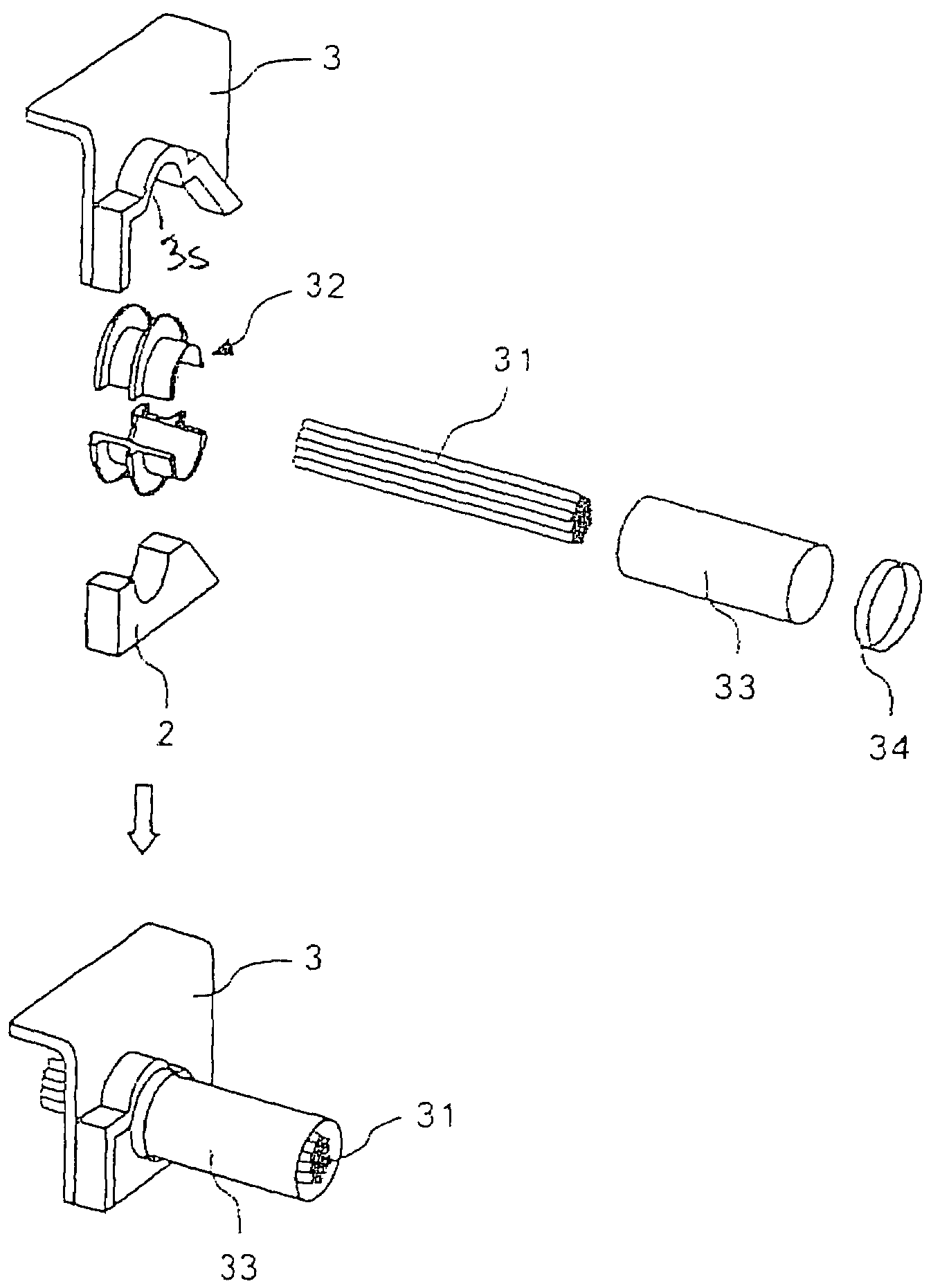
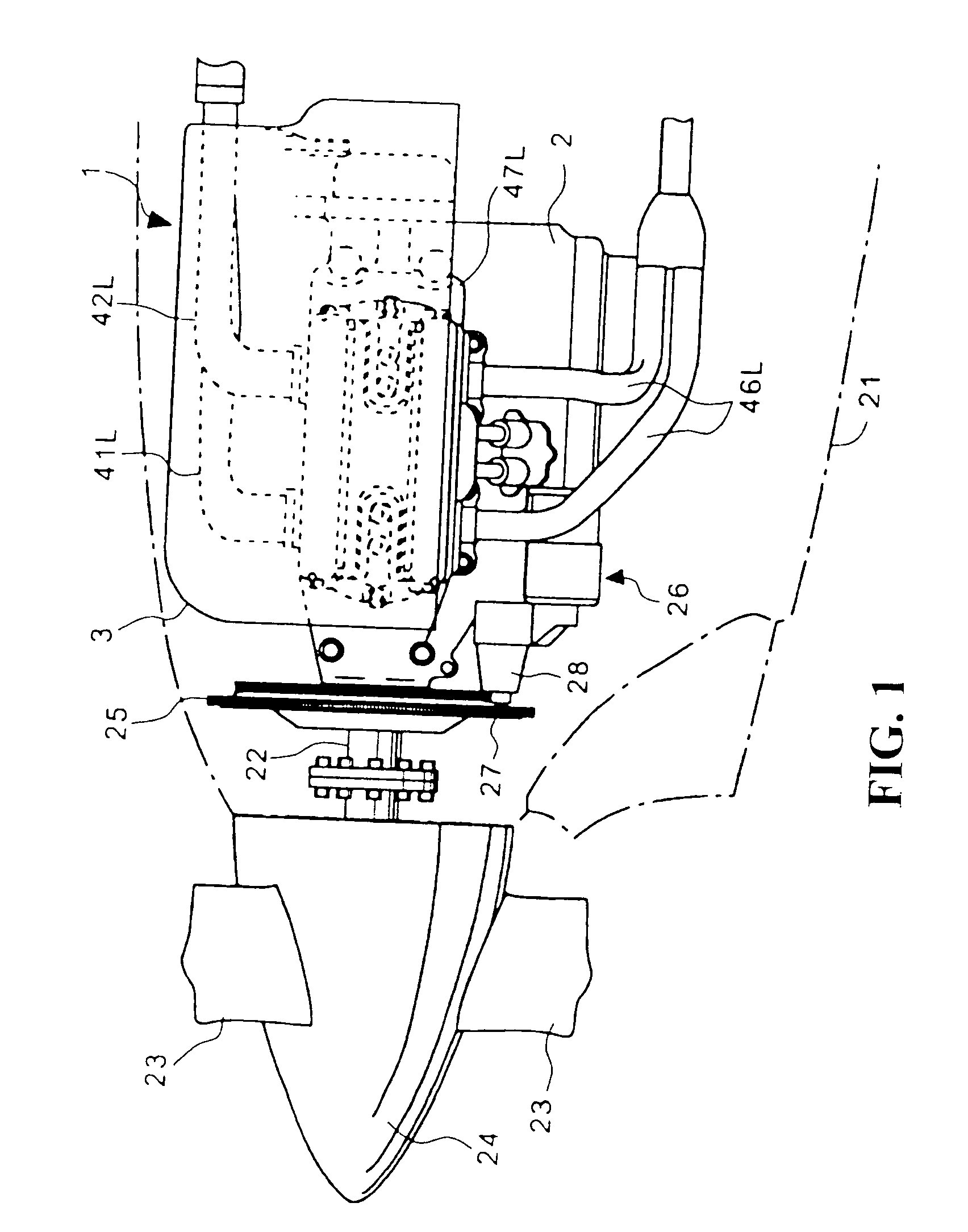
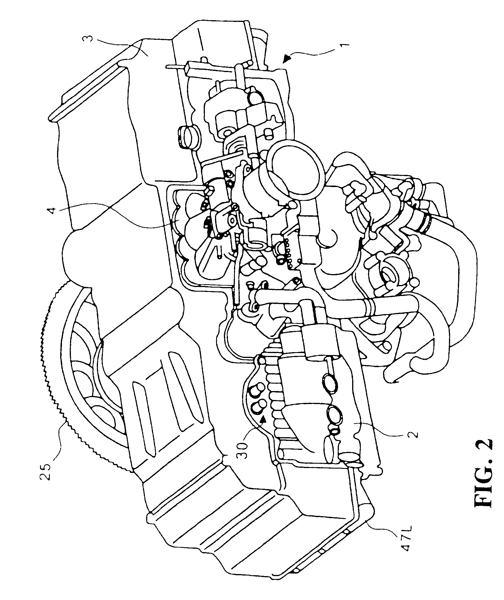
[0026]FIG. 1 is a side elevational view showing an aircraft engine, to which a harness outlet structure according to the preferred embodiment of the present invention is applied, mounted in an aircraft. FIG. 2 is a perspective view showing the aircraft engine as viewed from a left rearward and upward portion of the aircraft. FIG. 3 is a plan view of the aircraft engine.

[0027]An aircraft engine 1 includes a horizontally opposed 4-cylinder, 4-cycle engine main body 2 and a shield cover 3. The shield cover 3 covers to shield completely major portions of an upper portion and right and left side faces of the engine main body 2 such that there are produced no clearances. The engine main body 2 is housed in a cowl 21 mounted on a front portion of a fuselage so that an axis of a crankshaft 22 extends along the fore-aft direction. A spinner 24 including a plurality of propellers 23 is disposed forward of the cowl 21. The spinner 24 is coaxially coupled, together with a ring gear 25, to the c...


PUM


Abstract

A harness outlet structure of an engine permitting a reliable shield at a harness outlet of the engine. The structure includes a wiring harness is clamped by a shield cover and an engine main body via a grommet bracket. The grommet bracket includes a groove having a width equivalent to the thickness of the shield cover disposed circumferentially between two flange portions of the grommet bracket. A harness overall for shielding the wiring harness is mounted externally on a proximal end of the grommet bracket. The harness overall is a shield outer jacket body formed from braided metal fibers. The harness overall is inserted over an outside of the proximal end of the grommet bracket until one end of the harness overall contacts the flange portion. The harness overall is then joined by a coupling ring.

Description

CROSS-REFERENCE TO RELATED APPLICATION[0001]The present application claims priority under 35 U.S.C. §119 to Japanese Patent Application No. 2005-106029, filed Apr. 1, 2005, the entire contents of which are hereby incorporated by reference.BACKGROUND OF THE INVENTION[0002]1. Field of the Invention[0003]The present invention relates generally to a harness outlet structure of an engine and, more particularly, to a structure that gives an area near an outlet of a harness a highly reliable electromagnetic wave shielding function.[0004]2. Description of Background Art[0005]Effective measures against electromagnetic waves and large currents should be taken for electric components provided as accessories for aircraft engines. Japanese Patent Laid-open No. 2004-251271 discloses an art, in which electromagnetic fuel injection valves, ignition coils, and other electric components disposed in areas around an intake chamber of an engine are covered and shielded with a shield cover mounted on an ...

Claims


Application Information

Patent Timeline
Patent Type & Authority Patents(United States)
IPC IPC(8): H02G3/00
CPCH02G3/0666H02G3/22
Inventor HAMAZU, AKIRAMIKAME, MAMORUHAYASHI, DAISUKEYOKOYAMA, KIYOAKIURUNO, HIROSHI
Owner HONDA MOTOR CO LTD
Why Eureka
Try Eureka