Folding knife with locking blade

a technology of locking blade and folding knife, which is applied in the direction of thrusting weapons, white arms/cold weapons, weapons, etc., can solve problems such as user injuries, and achieve the effect of improving the locking mechanism of the blad

Inactive Publication Date: 2008-03-11
BUSSE JERRY P
View PDF32 Cites 30 Cited by
  • Summary
  • Abstract
  • Description
  • Claims
  • Application Information

AI Technical Summary

Benefits of technology

[0010]It is, therefore, the principal object of this invention to provide a folding knife having an improved blade locking mechanism.
[0012]Another object of the present invention is to provide a folding knife having a blade locking mechanism with an improved means for preventing the blade from becoming inadvertently unlocked.

Problems solved by technology

However, if care is not used in cutting with such a knife, or if the blade is used to apply force to an object in certain directions (and in particular if force is applied to the tip of the blade), the blade can inadvertently move from the open position towards the closed position, which can cause injury to the user.

Method used


Image

  • Folding knife with locking blade
  • Folding knife with locking blade
  • Folding knife with locking blade

Examples


Embodiment Construction

[0041]The accompanying drawings and the description which follows set forth this invention in its preferred embodiment. However, it is contemplated that persons generally familiar with folding knives will be able to apply the novel characteristics of the structures illustrated and described herein in other contexts by modification of certain details. Accordingly, the drawings and description are not to be taken as restrictive on the scope of this invention, but are to be understood as broad and general teachings.

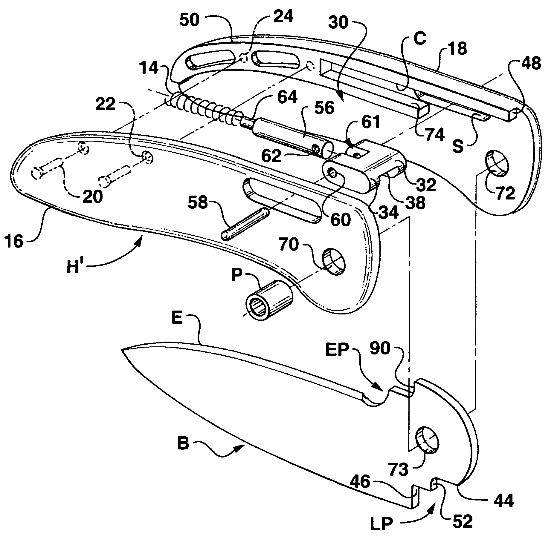
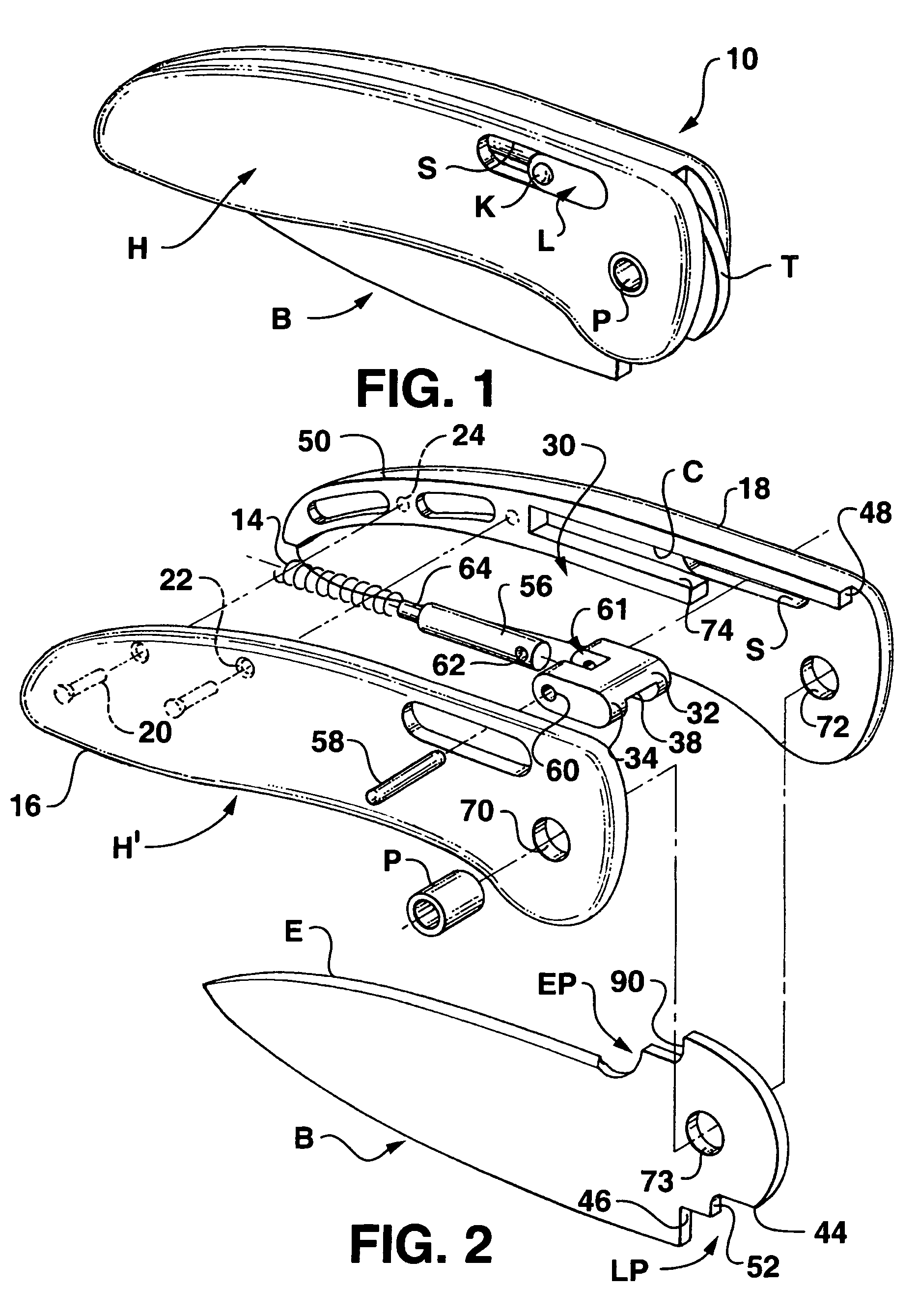
[0042]Referring now to the drawings in detail, wherein like reference characters represent like elements or features throughout the various views, the assembly, construction, and method of use of the locking folding knife of the present invention are discussed in detail. The locking folding knife is indicated generally in the figures by reference character 10.

[0043]Turning to FIG. 1 of the drawings, folding knife 10 is illustrated in one of the preferred embodiments of the p...


PUM


Abstract

A folding knife having a blade locking member carried for sliding movement within a channel defined in the handle, the locking member being movable to a blade locking position when the blade is in an extended position. A spring, or other biasing means, such as an opposing magnet arrangement, provide a spring-like biasing of the locking member towards a blade locking. In one embodiment, the locking member extends substantially the full width of the handle and is accessible from either side of the knife handle. The locking member includes a ramp on the underside thereof for contacting a projection, or bump, on the rearward portion of the blade tang. An adjustable bushing is provided which allows for adjustment of the blade within the handle to provide for both ease of pivoting of the blade, while reducing any lateral play in the blade within the handle.

Description

[0001]This application claims benefit of U.S. Provisional application Ser. No. 60 / 385,191, filed May 31, 2002, and is a continuation of application Ser. No. 10 / 452,653, filed Jun. 2, 2003 now U.S. Pat. No. 7,032,315, and the entirety of the foregoing applications is incorporated herein by reference thereto.BACKGROUND OF THE INVENTION[0002]This invention relates generally to a folding knife having a blade which automatically becomes locked once moved to an extended position.[0003]Folding knives come in two basic types. The first type includes a blade which may be moved between a closed or retracted position, substantially within the handle of the blade, and an open or extended position, extending outwardly from the handle. In this type of folding knife, the blade is not positively locked in place when in the extended position. In other words, by using some force, the blade can be moved from the extended position towards the retracted position without requiring release of a blade lock...

Claims


Application Information

Patent Timeline
Patent Type & Authority Patents(United States)
IPC IPC(8): B26B3/06
CPCB26B1/048
Inventor BUSSE, JERRY P.
Owner BUSSE JERRY P
Why Eureka
Try Eureka