Optical head device, optical recording device, and optical recording method

a recording device and optical head technology, applied in the direction of optical beam sources, instruments, disposition/mounting of heads, etc., can solve the problems of degrading data recording characteristics, reducing learning hours, and difficult to arrange a plate member or wedge-like block between the focusing lens and the optical lens. achieve the effect of increasing learning hours and acquiring the optimum recording characteristics of an optical recording

Inactive Publication Date: 2008-03-11
PANASONIC CORP
View PDF7 Cites 6 Cited by
  • Summary
  • Abstract
  • Description
  • Claims
  • Application Information

AI Technical Summary

Benefits of technology

[0010]In view of the above problems, an object of the present invention is to provide an optical head device, an optical recording device, and an optical recording method that enable acquisition of optimum recording characteristics of an optical recording medium having multiple data layers, with respect to each of the multiple data layers without increasing learning hours required for learning a relation between an aberration amount and an optimum recording compensation amount with respect to each of the multiple data layers.

Problems solved by technology

Increase of NA of a focusing lens may resultantly increase spherical aberration relative to a variation (unevenness) in thickness of a substrate of an optical disk.
A spherical aberration or a coma aberration may degrade data recording characteristics.
Therefore, it is difficult to arrange a plate member or wedge-like blocks between the focusing lens and the optical lens, considering vertical displacement of the optical disk arising from rotation of the optical disk, or vibrations exerted from the outside.
Despite such a merit, however, the above arrangement fails to set the total aberration including aberration of the fifth and higher orders to 0, with the total aberrations with respect to the data layers being different from each other.
Therefore, the recording characteristics compensating method in which the output of the light source is controlled based on the detected aberration amount, as having been employed in the conventional art, fails to carry out optimum recording characteristics compensation, because output control is not executed when the detected aberration amount of a low order is 0 although there actually remain aberrations of a higher order which are different from each other with respect to the data layers.
Thus, the conventional arrangement not only necessitates a program for learning a relation between the aberration amount and the optimum recording power with respect to each of the data layers, and for storing the learning results, but also makes the program complicated.
In this way, the technical field of the present invention has encountered problems such as increase of learning hours and increase of the quantity of the program, with increase in the number of data layers.

Method used


Image

  • Optical head device, optical recording device, and optical recording method
  • Optical head device, optical recording device, and optical recording method
  • Optical head device, optical recording device, and optical recording method

Examples


first embodiment

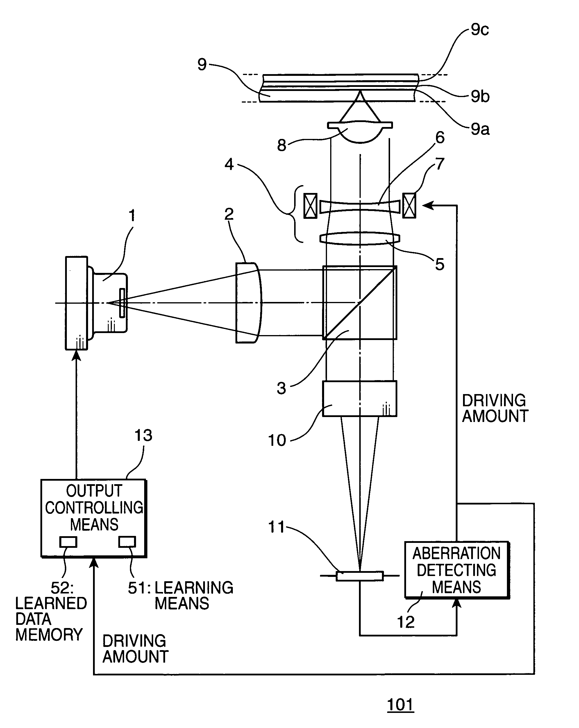
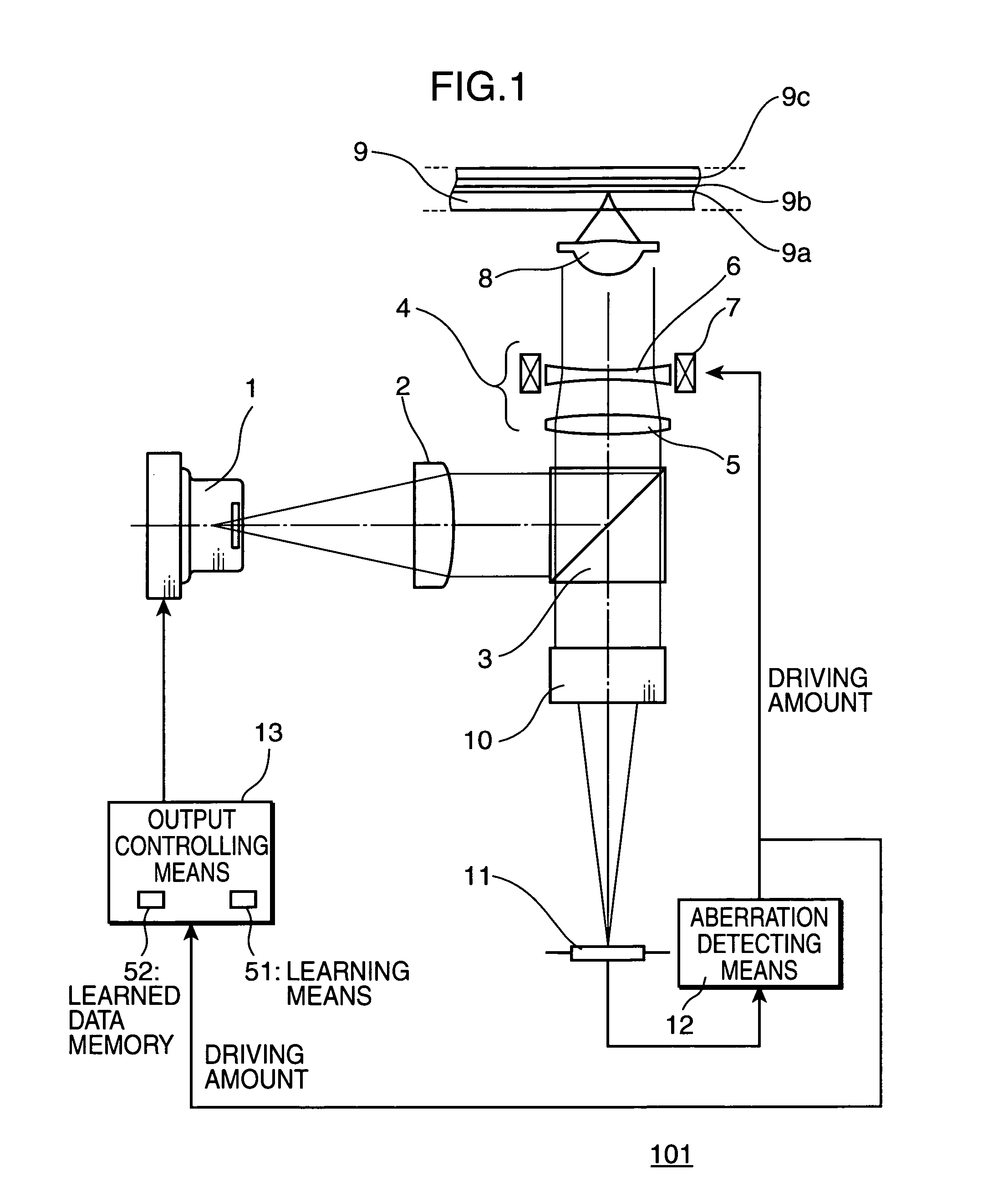
[0025]FIG. 1 is an illustration showing an arrangement of an optical head device in accordance with a first embodiment of the present invention. The optical head device 101 includes a light source 1, a collimator lens 2, a beam splitter 3, wavefront converting means 4, a focusing lens 8, a detection optical system 10, a light detector 11, aberration detecting means 12, and output controlling means 13. The light source 1 is preferably a semiconductor laser which emits laser light of wavelength 405 nm. The collimator lens 2 is adapted to make the laser light emitted from the light source 1 to parallel beams. The beam splitter 3 is adapted to split the optical path of light. The wavefront converting means 4 has a converging lens 5, a diverging lens 6, and driving means 7. The driving means 7 is adapted to drive the diverging lens 6. The driving means 7 is preferably a voice coil motor.

[0026]An optical recording medium 9 from which or in which data is to be read or written with use of t...

second embodiment

[0053]FIG. 9 is an illustration showing an arrangement of an optical head device in accordance with a second embodiment of the present invention. Referring to FIG. 9, elements identical to or equivalent to those in FIG. 1 are denoted by the same reference numerals, and description thereof will be omitted herein. Wavefront converting means 14 shown in FIG. 9 is constructed such that a liquid crystal device 61 is provided between electrodes 62a and 62b. As is well known, the phase of linear polarized light can be changed by applying a voltage to the liquid crystal device. Accordingly, spherical aberration can be corrected by providing well-known coaxially aligned annular electrodes as the electrodes 62a, 62b, and by changing the drive voltage to be applied to each of the annular electrodes. Likewise, as is well known in the art, a coma aberration can be corrected by dividing each of the annular electrodes radially into plural zones. Since the optical head device 102 in accordance with...

third embodiment

[0054]An optical recording device using the inventive optical head device is described as a third embodiment of the present invention referring to FIG. 10. As shown in FIG. 10, the optical recording device 103 includes an optical head device 15, rotation driving means 17, a circuit substrate 18, and a power source 19. The optical head device 15 is the optical head device 101 or the optical head device 101A as the first embodiment, or an optical head device 102 as the second embodiment. The rotation driving means 17 has a motor for drivingly rotating an optical disk 16 as an example of the optical recording medium while supporting the optical disk 16. The optical disk 16 has multiple data layers.

[0055]The optical head device 15 sends, to the circuit substrate 18, a signal indicative of a position thereof relative to the optical disk 16. The circuit substrate 18 computes the signal, and outputs a signal for minutely moving the optical head device 15 or a focusing lens 8 in the optical...


PUM

PropertyMeasurementUnit
wavelengthaaaaaaaaaa
thicknessaaaaaaaaaa
thicknessaaaaaaaaaa

Abstract

An object of the present invention is to acquire optimum recording characteristics of an optical recoding medium having multiple data layers, with respect to each of the multiple data layers without increasing learning time required for learning a relation between aberration amount and optimum recording compensation with respect to each of the multiple data layers. The present invention includes a wavefront converter which is driven in such a manner as to reduce the aberration amount detected by an aberration detector. An output controller holds learned data as to the relation between the driving amount of the wavefront converter and the output of a light source, and controls the output of the light source based on the driving amount of the wavefront converter and the learned data.

Description

TECHNICAL FIELD[0001]The present invention relates to an optical head device, an optical recording device, and an optical recording method for recording and / or erasing information on an optical medium or an opto-magnetic medium such as an optical disk or an optical card, and particularly to an optical head device, an optical recording device, and an optical recording method suitable for recording and / or erasing data on an optical recording medium having multiple data layers (e.g., a multi-layered optical disk or a multi-layered optical card).BACKGROUND ART[0002]There has been developed use of a light source of a shorter wavelength, and a focusing lens having a larger numerical aperture (hereinafter, simply called as “NA”) in order to increase the recording capacity of an optical disk. The wavelength of the light source and NA of the focusing lens used in DVDs are generally 650 nm and 0.6, respectively. There has been proposed an optical system for optical disks of future generation ...

Claims


Application Information

Patent Timeline
Patent Type & Authority Patents(United States)
IPC IPC(8): G11B7/135G11B7/00G11B7/09G11B7/125G11B7/1267G11B7/1369G11B7/1372G11B7/1378G11B7/1392
CPCG11B7/1267G11B7/1369G11B7/1378G11B7/13927G11B7/0948G11B2007/0013G11B2007/13727
Inventor ITO, TATSUOSHIONO, TERUHIROYAMAMOTO, HIROAKINISHINO, SEIJI
Owner PANASONIC CORP
Why Eureka
Try Eureka