Device for loading and unloading containers

a container and device technology, applied in the direction of drying machines, drying machines with progressive movements, drying solid materials, etc., can solve the problems of high maintenance cost of such rooms, access to freeze-dryers, and small spa

Active Publication Date: 2008-03-18
IMA TELSTAR
View PDF12 Cites 24 Cited by
  • Summary
  • Abstract
  • Description
  • Claims
  • Application Information

AI Technical Summary

Benefits of technology

[0030]Thanks to these characteristics, the device of this invention has the following advantages:
[0031]The loading and unloading system is completely automatic, so that an operative does not have to be present.
[0032]The working speed is not limited, because during the loading process, the movement of the containers is carried out with the presence of said second means that act as a stop for said containers, in order to ensure that they advance aligned and to prevent them from spilling.
[0033]The device occupies limited space in clean rooms, is easy to implement on an isolator and can be easily disassembled to submit its parts to cleaning and sterilisation.
[0040]Thanks to these characteristics, a mechanism that allows the bar attached to the carriages to be raised above the containers is achieved. Said bar can thus be retracted from the interior shelf of the treatment installation once loading has been completed, or travel to the back of the interior shelf at the start of unloading. This mechanism has the advantages of being simple, taking up no space and being easy to disassemble.

Problems solved by technology

For this reason, the parts of such installations that are in contact with the product and its container are normally placed in clean rooms, whose space is usually very small for reasons mainly associated with the high maintenance cost of such rooms.
Moreover, again due to the need to ensure product hygiene, it should be taken into account that such devices must avoid to the utmost extent loading and unloading parts that remain inside the freeze-dryer during the treatment, as access into the freeze-dryer is difficult and means that such parts cannot be cleaned adequately.
The device of the cited US patent has the disadvantage that it occupies a large space in clean rooms since it comprises a formatting table and a transfer table that has to be brought into proximity with the freeze-drying apparatus once loaded with containers.
Furthermore, the working speed is extremely slowly because during the loading and unloading process a large number of steps must be taken.
The sealed mechanical feedthrough for the rear cylinder which traverses the freeze-dryer chamber increases the risk of leaks in the chamber and, therefore, also increases the danger of lack of product and process sterility.
Furthermore, the presence of this part in the rear part of the freeze-drying chamber makes it impossible to mount the device on an existing freeze-dryer, since the space inside a freeze-dryer is very small and does not permit the mounting of new parts for which provision has not been made in advance.
The mechanical modifications which this addition would entail for the freeze-dryer chamber would also be too costly.
The working cycle of the device of the above-mentioned patent has the disadvantage of having a time lag upon completion of loading of each shelf, as the rear cylinder and bar have to retract to their initial positions in order to allow the vertical movement of the loaded shelf and to await the positioning of a new shelf for loading containers.
This time lag between the loading of shelves can be lengthy, and this has a negative effect on the efficiency of the device.
The working speed is limited, because during the loading process both the travel of the containers on the fixed platform and the travel of the flexible sheet itself with the loaded containers is carried out without the presence of a bar to act as a stop for said containers.
The unloading process has the disadvantage of not being completely automatic, since at the end of the unloading process it requires the assistance of an operative to push the last rows of containers left on the fixed platform towards the conveyor belt.
When the flexible sheet is left free of containers, however, and even if it does retract, it cannot push the last rows of containers to be unloaded, since those containers are deposited only on the fixed platform.
Another disadvantage of the device described in the German Utility Model is that it is an equipment that cannot be disassembled easily in order to submit its parts to cleaning and sterilisation each time the treatment installation is loaded.
For instance, there is the need to have space to spread out the sheet, which can be large; such space can be difficult to achieve in the light of the space-restriction that exists in clean rooms.

Method used


Image

  • Device for loading and unloading containers
  • Device for loading and unloading containers
  • Device for loading and unloading containers

Examples


Embodiment Construction

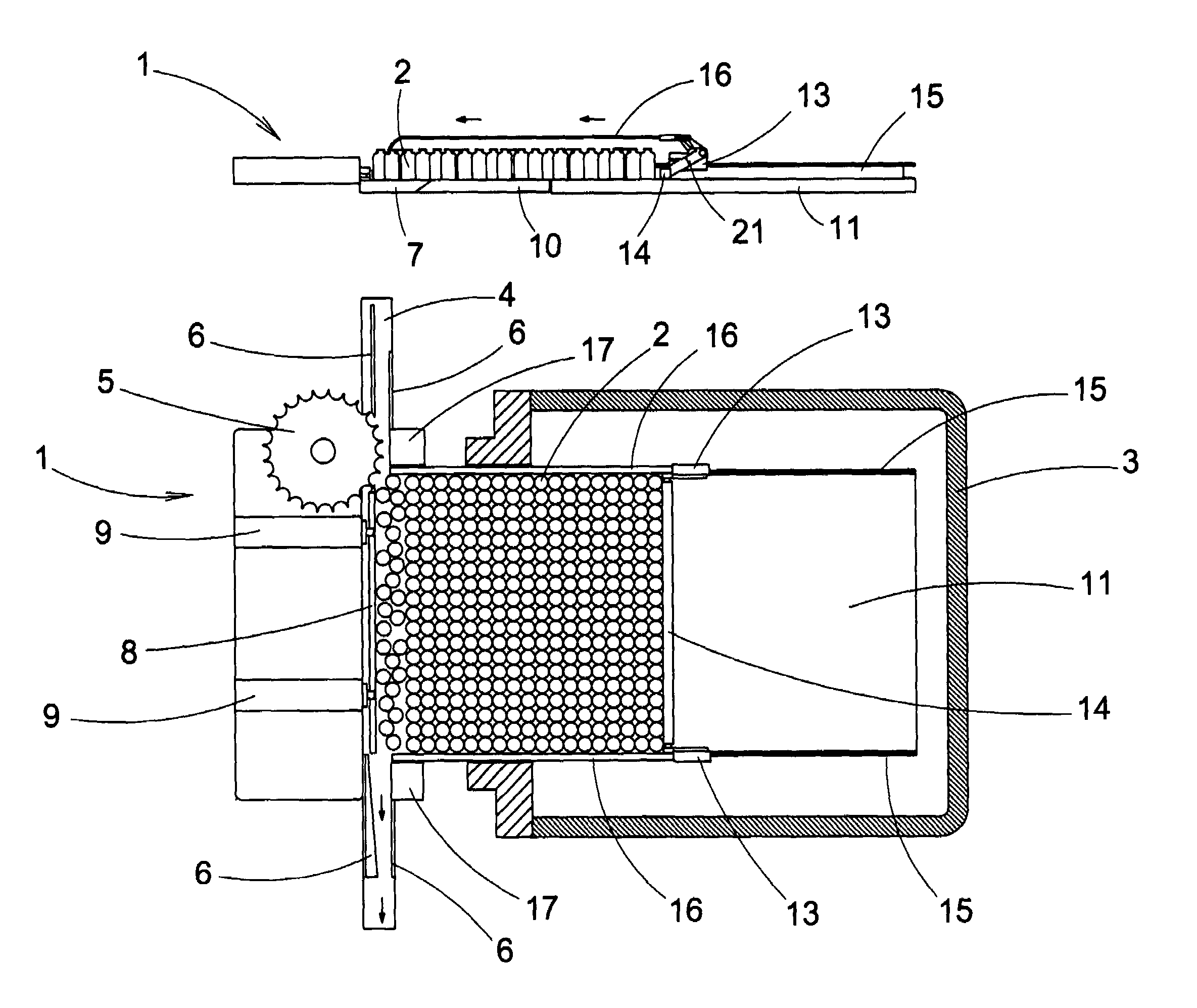
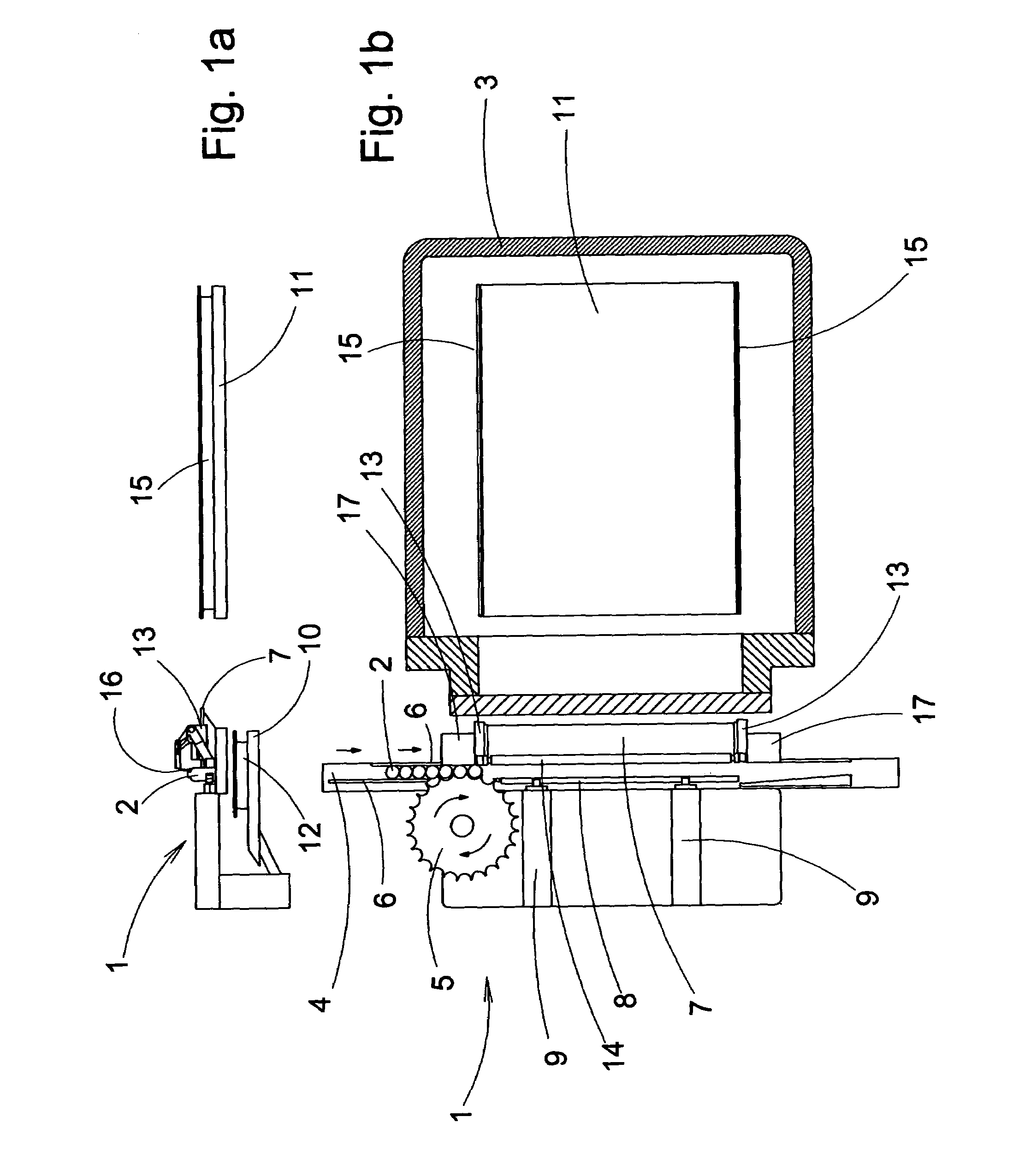
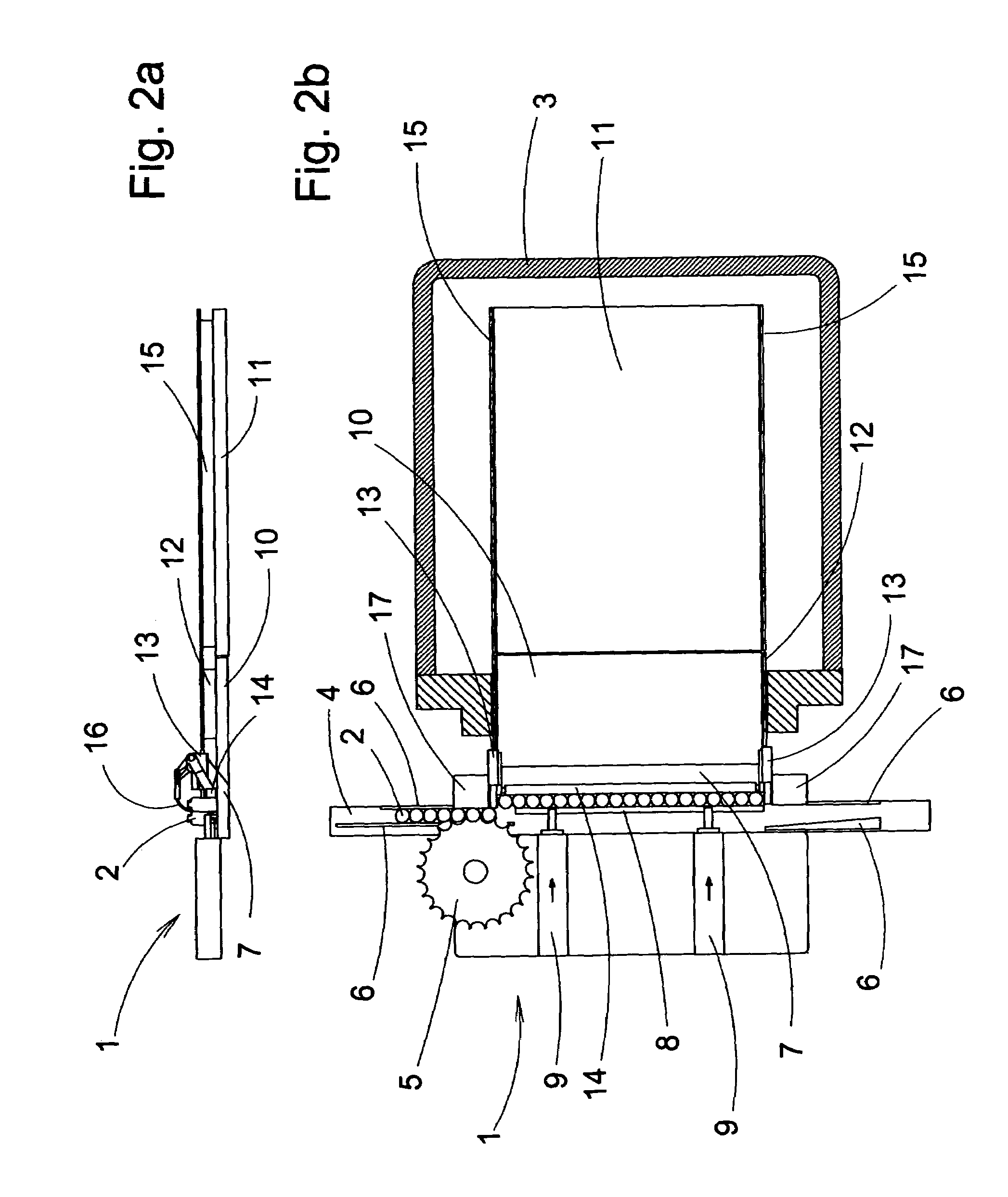
[0028]The objective of this invention is to resolve the disadvantages mentioned by developing a device for loading and unloading containers into and out of an enclosure of an installation for treating the substances contained in said containers, which has the advantages described below.

[0029]In accordance with this objective, the device of this invention includes a support structure, means for positioning said containers on the device, a fixed platform, first means for moving said containers during a loading process, second means for moving the containers during a unloading process and third means for moving said second means to a position higher than said containers and for moving outside the enclosure of the treatment installation said second means, said second means acting as a stop during loading and as a pusher during unloading, and is characterised in that said device includes an extendible platform, said extendible platform unfurling from said support structure to form, durin...


PUM


Abstract

A device (1) for loading and unloading containers (2) into and out of an enclosure of an installation (3) for treating substances contained in containers (2). The device includes a support structure (17) and a third means (16, 19, 21) for moving a second means (14) to a position higher than the containers. The second means (14) acts as a stop during loading and as a pusher during unloading. The device includes an extendible platform (10), wherein the extendible platform unfurls from the support structure (17) and the third means comprise parts (16a 16b) that unwind from the support structure (17) to the interior of the enclosure. The device is completely automatic, fast, takes up little space and is easy to disassemble.

Description

[0001]This invention relates to a device for loading and unloading containers into and from an enclosure of an installation for treating substances contained in such containers.BACKGROUND OF THE INVENTION[0002]Known in the art are devices for loading and unloading containers at plants for treating substances, such as plants for drying products, called freeze-dryers.[0003]Freeze-dryers are used for drying products, typically pharmaceutical or food products. Pharmaceutical products are placed in the freeze-dryer in glass containers, on flat shelves situated one above another to form the equivalent of shelving. Most freeze-dryers have means for moving said flat shelves vertically, so that they can either be stacked or placed one by one at a particular loading height.[0004]The freeze-drying process, particularly for pharmaceutical products, requires maximum sterility of the product and its container but also of its manipulating elements, such as loading and unloading systems and treatme...

Claims


Application Information

Patent Timeline
Patent Type & Authority Patents(United States)
IPC IPC(8): F26B13/30F26B5/06F26B25/00
CPCF26B5/06F26B25/001
Inventor COVERT, WILLIAM JOHN
Owner IMA TELSTAR
Why Eureka
Try Eureka