
Inkjet printer cartridge refill dispenser with security lock for spent refill

a printer cartridge and security lock technology, applied in printing and other directions, can solve the problems of avoiding refilling, avoiding refilling, and slow system, and avoiding refilling

Inactive Publication Date: 2008-03-18
MEMJET TECH LTD +1
View PDF22 Cites 2 Cited by
  • Summary
  • Abstract
  • Description
  • Claims
  • Application Information

AI Technical Summary

Benefits of technology

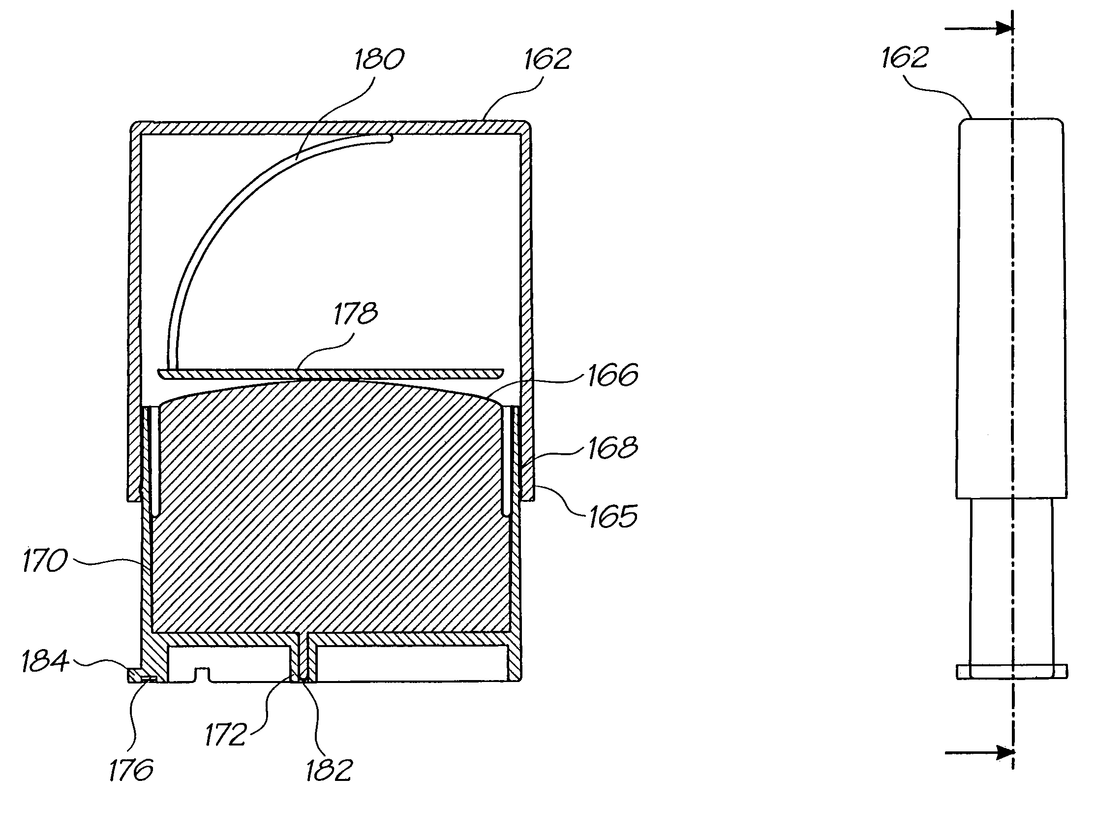
[0019]It will be appreciated that the printing fluid dispenser of the present invention provides a means for dispensing a range of printing fluids to refill an external reservoir, such as a storage reservoir in an inkjet printer cartridge having a pagewidth printhead. The dispenser employs a mechanism by which, following operation of the dispenser and the discharging of the printing fluid contained therein, the body of the dispenser remains in an empty state with the plunger depressed. Such an arrangement prevents the dispenser from being reused and recharged with an ink that is not supported by the inkjet printer, which could potentially cause damage the printhead and premature replacement of the printhead.

Problems solved by technology

Replacement of the printhead may be necessary due to degradation of the printhead through usage and in some cases the printhead may require replacement following depletion of the ink supply.
Whilst printer systems employing such traditional traversing printheads have proven capable of performing printing tasks to a sufficient quality, as the printhead must continually traverse the stationary print media, such systems are typically slow, particularly when used to perform print jobs of photo quality.
However as the printhead is the length of the print media, it must be supported within the structure of the printer unit and requires multiple electrical contacts to deliver power and data to drive the printhead, and as such removal and replacement of the printhead is not as easy as with traditional traversing printheads.

Method used


Image

  • Inkjet printer cartridge refill dispenser with security lock for spent refill
  • Inkjet printer cartridge refill dispenser with security lock for spent refill
  • Inkjet printer cartridge refill dispenser with security lock for spent refill

Examples


Embodiment Construction

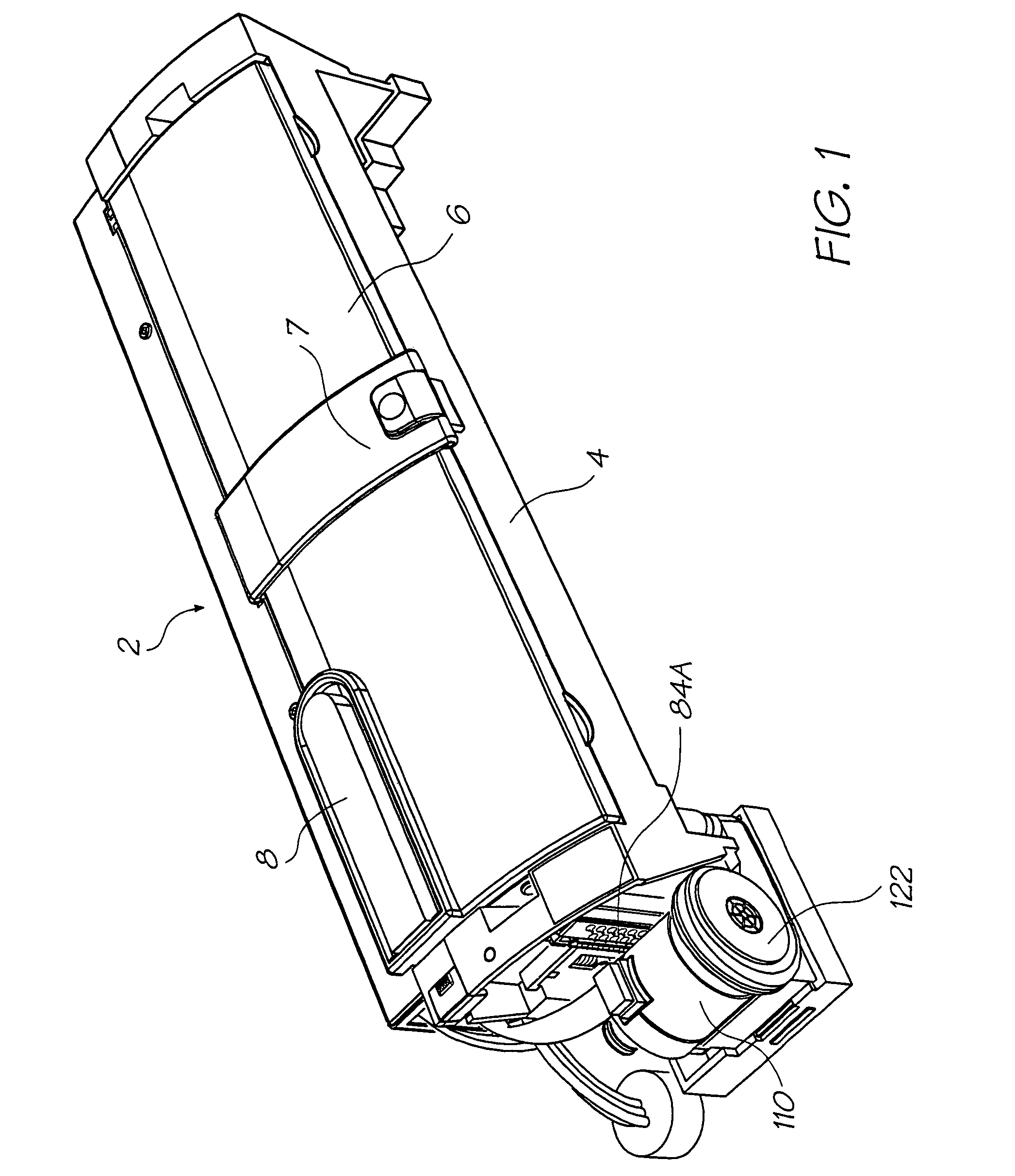
[0062]FIG. 1 depicts an inkjet printer 2 which includes a cradle 4 that receives a replaceable print cartridge 6 into a recess formed in the cradle's body according to a preferred embodiment of the present invention. Cartridge 6 is secured in the cradle recess by a retainer in the form of latch 7 that is connected by a hinge to cradle 4.

[0063]Visible on the upper surface of print cartridge 6 is an ink refill port 8 which receives an ink refill cartridge during use.

Print Cartridge

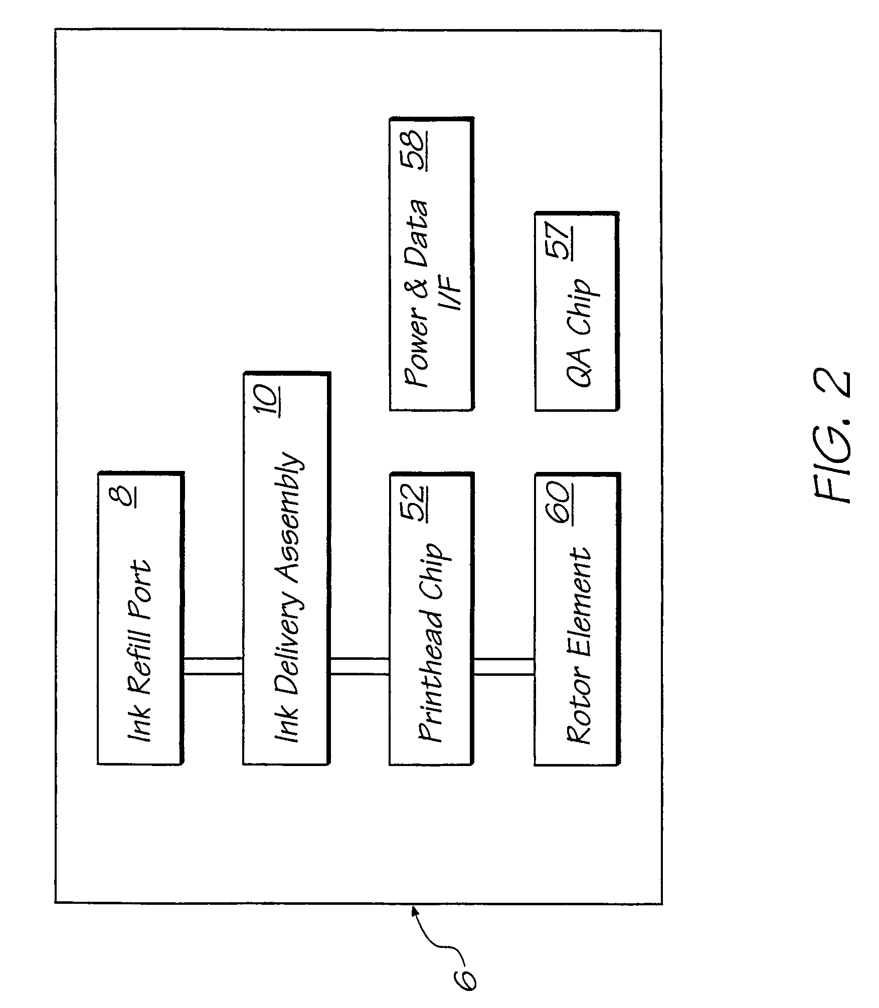
[0064]Referring now to FIG. 2, there is depicted a block diagram of removable inkjet printer cartridge 6.

[0065]Cartridge 6 includes ink refill port 8 and an ink delivery assembly 10 for storing and delivering ink to a micro-electromechanical pagewidth print head chip 52. Printhead chip 52 receives power and data signals from cradle 4 (see FIG. 1) via power and data interface 58. A rotor element 60, which is mechanically driven by cradle 4 has three faces which respectively serve to: blot printhead chip 52 su...


PUM


Abstract

A printing fluid dispenser including a deformable container for printing fluid; a housing locating the deformable container between a base slidingly engaging a plunger; and an outlet coupled to the deformable container and arranged to convey the printing fluid to a point external to the housing; wherein the base and plunger engage each other by means of one or more complementary protrusions and indentations formed into opposing walls of the base and plunger and positioned to prevent disengagement of the plunger from the base subsequent to operation of the dispenser.

Description

FIELD OF THE INVENTION[0001]The present invention relates to a printer system and in particular to a printing fluid dispenser for refilling a removable printer cartridge for an inkjet printer system.CROSS-REFERENCE TO CO-PENDING APPLICATIONS[0002]The following applications have been filed by the Applicant simultaneously with the present application:[0003]10 / 76027210 / 760273708327110 / 760182708089410 / 760218709033610 / 76021610 / 76023310 / 760246708325710 / 76024310 / 76020110 / 76018510 / 76025310 / 76025510 / 760209711819210 / 76019410 / 760238707750510 / 760235707750410 / 76018910 / 76026210 / 76023210 / 76023110 / 76020010 / 76019010 / 76019110 / 7602277108353710462910 / 76025410 / 76021010 / 76020210 / 76019710 / 76019810 / 76024910 / 76026310 / 76024710 / 76022310 / 76026410 / 760244709729110 / 76022210 / 760248708327310 / 76019210 / 76020310 / 76020410 / 76020510 / 76020610 / 76026710 / 76027010 / 76025910 / 76027110 / 76027510 / 760274712165510 / 76018410 / 76019510 / 76018610 / 760261708327210 / 760180711193510 / 76021310 / 76021910 / 76023710 / 76022110 / 760220700266410 / 76025210 / 7...

Claims


Application Information

Patent Timeline
Patent Type & Authority Patents(United States)
IPC IPC(8): B41J2/175
CPCB41J2/17506
Inventor SILVERBROOK, KIA
Owner MEMJET TECH LTD
Learn More