
Method for cleaning of a measuring element passed over by a gas flow

a technology of gas flow and measuring element, which is applied in the direction of cleaning process and apparatus, cleaning using liquids, instruments, etc., can solve the problems of localized warping, and achieve the effects of reducing the contamination rate of the measuring chip on the upper side of the membranous material, and reducing the deflection of the measuring signal

Inactive Publication Date: 2005-11-15
ROBERT BOSCH GMBH
View PDF2 Cites 6 Cited by
  • Summary
  • Abstract
  • Description
  • Claims
  • Application Information

AI Technical Summary

Benefits of technology

The present invention proposes a solution for cleaning a heating element of a sensor element without the need for a separate cleaning device. The periodic delivery of current to the heating element causes a thermal expansion of the membrane, which results in a short, continuous bowing of the membrane, which can be initiated by various features, such as temperature change. This bowing action takes place very quickly and is dependent on the intervals of current delivery and the current delivery pauses. The membrane material can also be stimulated into vibration by ultrasonic waves, which can mechanically couple in the membranous material or the measuring chip. The membrane material accommodating the measuring chip is cleaned by the acceleration of the membrane material with the measuring resistors accommodated thereon in the direction of the upper surface normals, which causes a debonding of adhered contaminants from the membranous material and the region of the resistors. This cleaning process reduces the deflection of the measuring signal and avoids premature replacement of the air mass sensor based on the drift.

Problems solved by technology

A temperature change with this type of membrane by means of the heating of the resistors immediately leads to localized warping.

Method used


Image

  • Method for cleaning of a measuring element passed over by a gas flow
  • Method for cleaning of a measuring element passed over by a gas flow
  • Method for cleaning of a measuring element passed over by a gas flow

Examples


Embodiment Construction

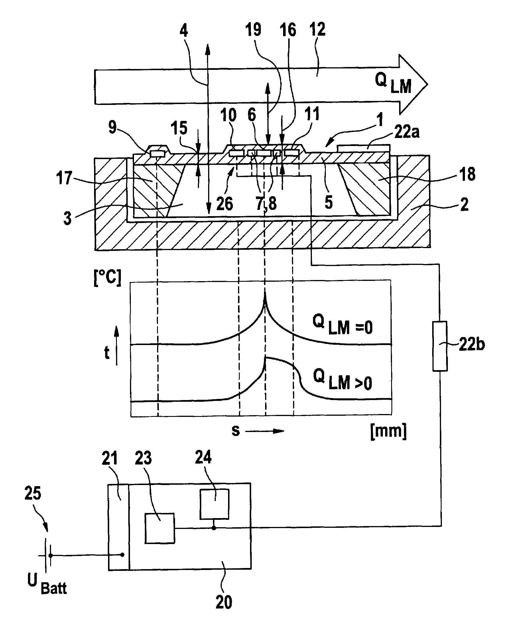
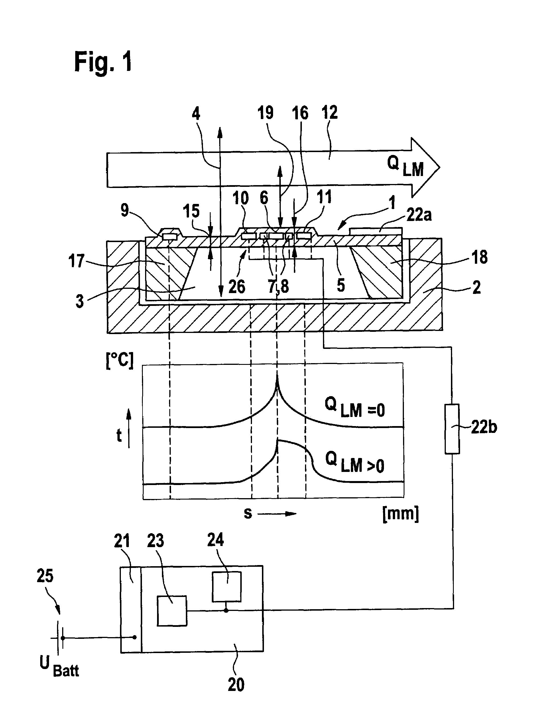
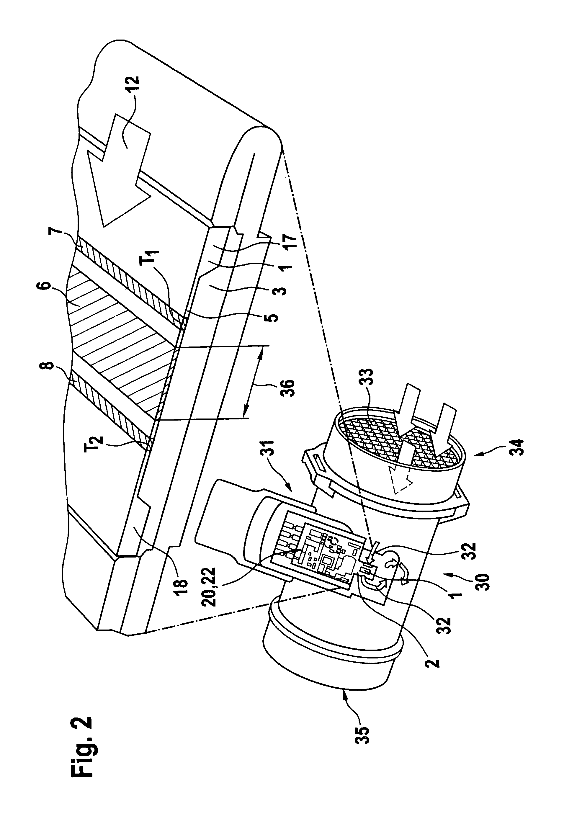
[0012]In FIG. 1, a measuring element 1 is shown, which represents a micro-mechanical heat film-air mass-flow meter. The measuring element 1 is the inner region of a membrane 5, which is mounted on the upper surface of a measuring chip 26, whereby between the underside of the measuring element 1 or of its membranous material 5 and the mounting receptacle 2, a free space allowing vibration is formed. The measuring chip is arranged within the mounting receptacle 2. The upper surface normal positioned perpendicular on the upper surface of the membranous material 5 is designated with reference numeral 4. A heat resistor 6 is located on the upper side of the measuring element 1, which is facing toward a gas flow symbolized with arrow 12, such as, for example, the intake air mass flow for an internal combustion engine. The heat resistor 6 can be supplied with voltage via a control apparatus 20, which is connected with an externally arranged voltage source, such as, for example, a motor veh...


PUM


Abstract

A method for cleaning of a measuring element (1) passed over by a gas flow is arranged on a thin-walled membranous material (5). The measuring element (1) includes at least one heatable element (6, 7, 8; 10, 11), which is arranged on the membranous material, the membranous material being capable of vibrating. By means of a control apparatus (20) or a switching (22) associated with the measuring element, a periodic delivery of current (41, 42) in intervals takes place in this manner to at least one heatable element (6, 7, 8; 10, 11) of the measuring element (1) and thereby produces vibrations. Alternatively, vibrations of the membranous material (5) can be produced by special vibration exciters or by means of ultrasonic coupling.

Description

BACKGROUND OF THE INVENTION[0001]Heat film-air mass-flow meters are used in motor vehicles, for example, in intake or charger apparatuses of the internal combustion engine. With the chemical process of combustion, the amount of air depending on the mass ratio of fuel and required for combustion is high. Therefore, in the intake apparatus / charging apparatus of the internal combustion engine, the mass flow rate of the intake air / charging air is determined. In addition to volume or dynamic pressure methods, methods that measure mass flow of the air current are also used.[0002]In the intake apparatus of internal combustion engines, today micro-mechanical heat film-air mass-flow meters, which work according to the thermal principle, are also used in part. These are very small and require little space. Heat and sensor resistors are mounted with these very small flow-meters as thin Pt-layers on a chip, which can be made from silicon and serve as a support. On the chip, a mechanically thinn...

Claims


Application Information

Patent Timeline
Patent Type & Authority Patents(United States)
IPC IPC(8): G01F1/696G01F1/684G01F1/698B08B3/12G01F1/68G01F15/12G01F1/692
CPCG01F1/6845G01F1/6986B08B3/12
Inventor HECHT, HANSSCHULZ, TORSTENLENZING, THOMASREYMANN, KLAUSKONZELMANN, UWE
Owner ROBERT BOSCH GMBH
Learn More