
Method and system for estimating wear of a drill bit

Pending Publication Date: 2022-08-25
EPIROC ROCK DRILLS AB
View PDF2 Cites 0 Cited by
  • Summary
  • Abstract
  • Description
  • Claims
  • Application Information

AI Technical Summary

Benefits of technology

The invention relates to a system for estimating the wear of a drill bit during percussion rock drilling. The system uses data such as the percussion frequency and the weight on bit to predict when the drill bit will need replacement to ensure continued drilling. The addition of parameters such as rate of penetration, weight on bit, feed force, and drilled depth can improve the accuracy of wear estimation. The current depth of the hole and the number of drill rods in the drill string can also be used as input parameters. This system helps to prevent the drill bit from becoming worn out and ensures that the next hole can be drilled without the risk of losing the drill bit's performance.

Problems solved by technology

However, in order to obtain an efficient drilling process, the drill bit must not be worn to an extent where drilling no longer can be carried out at as expected.

Method used


Image

  • Method and system for estimating wear of a drill bit
  • Method and system for estimating wear of a drill bit
  • Method and system for estimating wear of a drill bit

Examples


Embodiment Construction

[0056]Embodiments of the present invention will be exemplified in the following in view of a particular kind of drill rig where drilling is carried out through the use of a percussion device in the form of a down-the-hole (DTH) / in-the-hole (ITH) hammer. The invention is, however, applicable also for other kinds of drill rigs that comprises a DTH / ITH percussion device. According to embodiments of the invention, the drill rig is instead of a kind comprising a percussion device in the form of a top hammer. The drill rig may also be of any other kind where drilling is carried out through the use of a percussion device for generating shock waves into a drill tool for breaking rock. The invention is also applicable irrespective of whether drilling is carried out using a pneumatic or hydraulic percussion device.

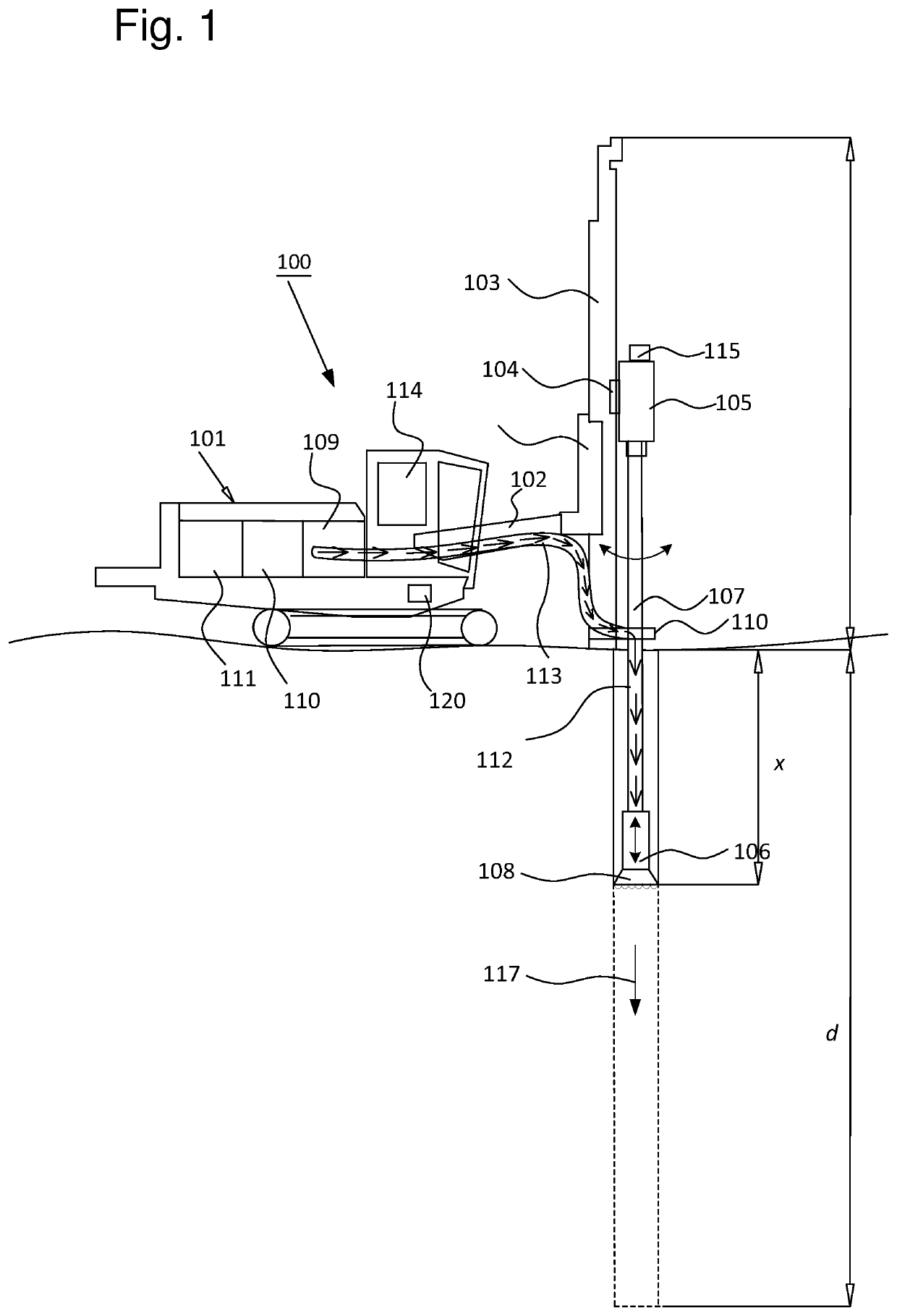
[0057]FIG. 1 illustrates a rock drilling rig 100 according to a first exemplary embodiment of the present invention for which an inventive method of determining wear of a drill bit ...


PUM


Abstract

A method for estimating wear of a drill bit in percussive rock drilling. A percussion device is configured for generating shock waves in a drill bit for breaking rock. The method includes, during drilling determining a percussion frequency of the percussion device; and estimating wear of the drill bit based on the determined percussion frequency of the percussion device and a model representation of the wear of the drill bit as a function of percussion frequency, wherein the model representation is configured to output the estimated wear of the drill bit utilizing the determined percussion frequency as input signal.

Description

FIELD OF THE INVENTION[0001]The present invention relates to percussive rock drilling, and, more specifically, to a method and system for estimating wear of a drill bit. The invention also relates to a drill rig, as well as a control system that implements the method according to the invention.BACKGROUND OF THE INVENTION[0002]Rock drilling rigs may be used in a number of areas of application. For example, rock drilling rigs may be utilised in tunnelling, surface mining, underground mining, rock reinforcement, raise boring, and be used e.g. for drilling blast holes, grout holes, holes for installing rock bolts, water wells and other wells, piling and foundations drilling etc. There is hence a vast use for rock drilling rigs.[0003]Furthermore, the actual breaking of the rock is oftentimes carried out by a drill bit contacting the rock, where the drill bit is connected to a drilling machine, in general by means of a drill string. The drilling can be accomplished in various ways, e.g. a...

Claims


Application Information

Patent Timeline
IPC IPC(8): E21B10/36E21B7/02
CPCE21B10/36E21B7/025E21B12/02E21B44/00G06F30/20E21B2200/20E21B1/00E21B44/005
Inventor STENBERG, GORANROSENDAL, ERIK
Owner EPIROC ROCK DRILLS AB
Learn More