Modular construction system utilizing versatile construction elements with multi-directional connective surfaces and releasable interconnect elements

a construction system and multi-directional technology, applied in the field of modular construction systems, can solve the problems of significant limitations on the way such building blocks can be releasably connected to one another, weak coupling force between smaller and significantly larger interconnected blocks, and severe inability to inspire peopl

Inactive Publication Date: 2008-03-25
INSPIRED CHILD
View PDF9 Cites 29 Cited by
  • Summary
  • Abstract
  • Description
  • Claims
  • Application Information

AI Technical Summary

Benefits of technology

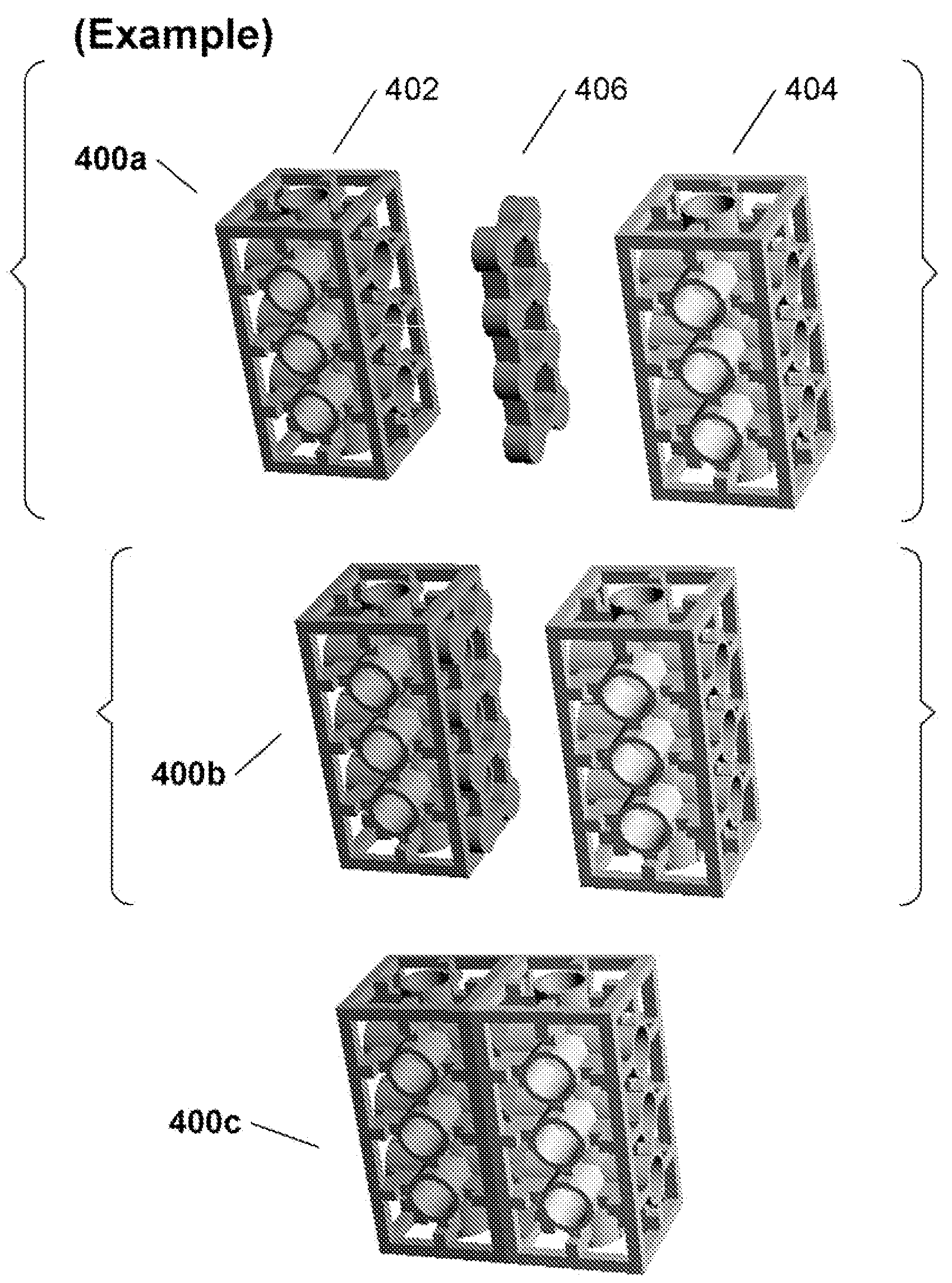
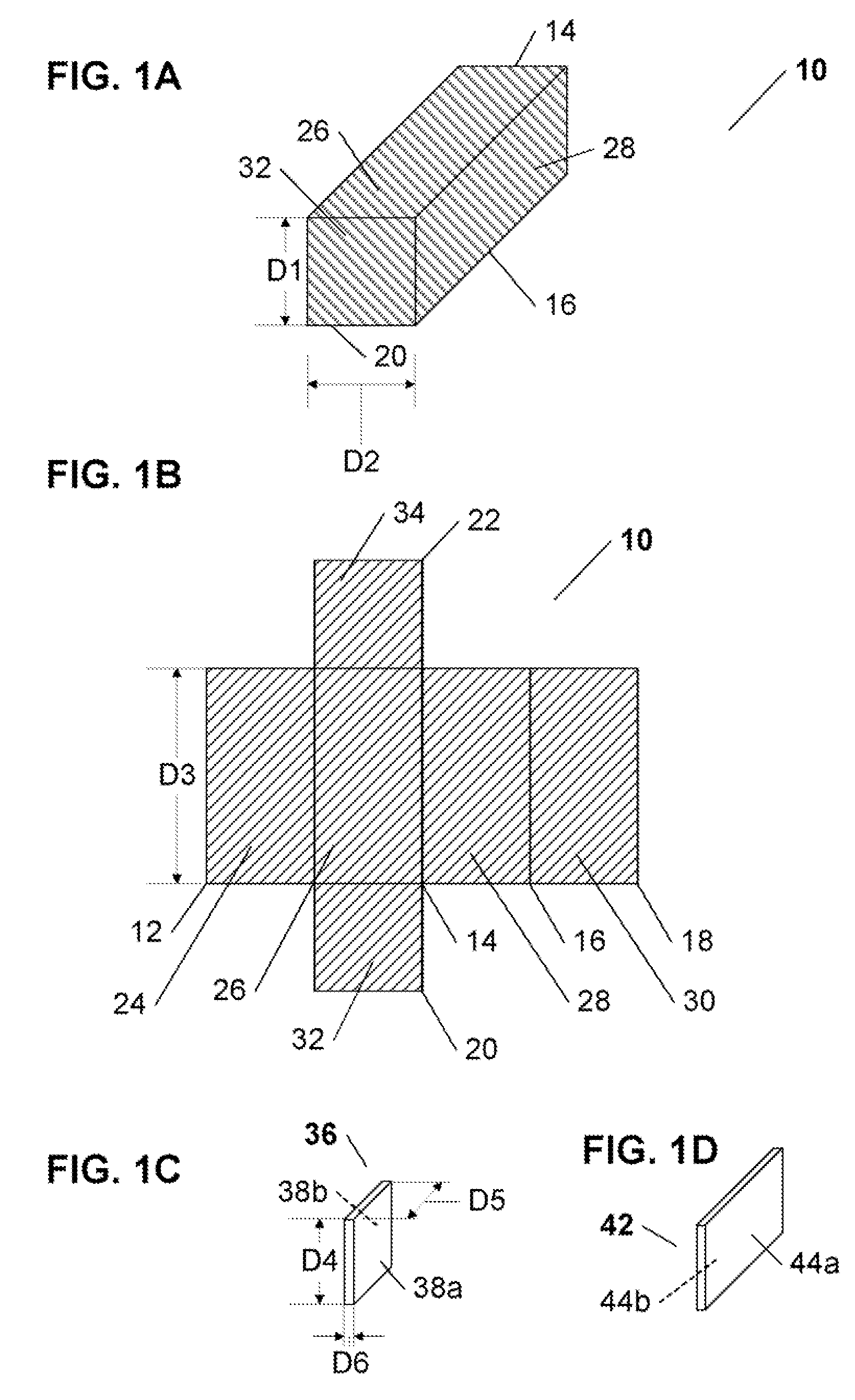
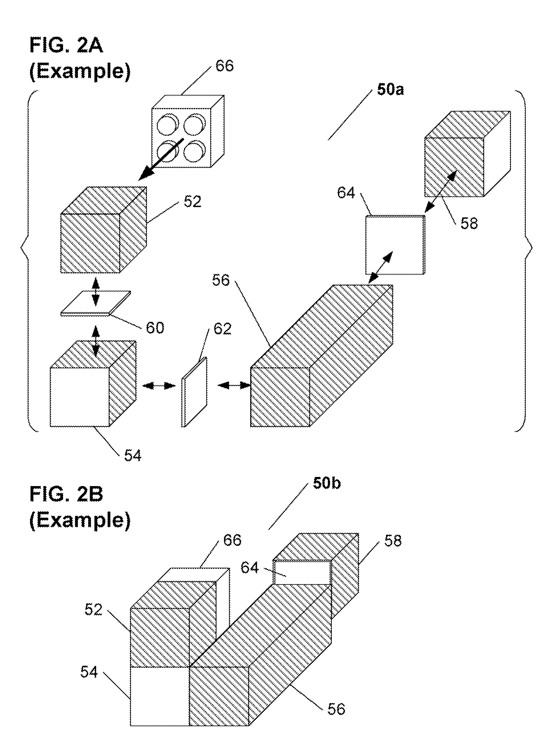
[0043]The present invention is directed to a modular construction system, that utilizes versatile construction components that are releasably attachable to one another in virtually any desired direction, by use of one or more interconnect components. Each inventive construction component includes at least two connective surfaces, each oriented in any desired direction, and each having a receiving region therein, while each interconnect component includes at least one coupling surface comprising multiple coupling elements capable of releasable frictional engagement with at least a portion of one or more of the receiving regions.

Problems solved by technology

First and foremost, there are very significant limitations on the how such building blocks can be releasably connected to one another—i.e., the blocks can only be connected in a stacking fashion, with the male coupling connectors of at least a portion of the blocks being in releasable engagement with female receiving connectors of another portion of the blocks.
This serious flaw severely inhibits the creativity of a person (e.g., a child) playing with the construction set, by forcing them to use the building elements in a very specific manner.
Another drawback of the majority of Category-1 building blocks is the relative weakness of coupling force between smaller and significantly larger interconnected blocks, and of the stability of their orientations with respect to one another.
Nevertheless, the inherent structure and construction of the majority of commonly used Category-1 building blocks eliminates the possibility of expanding the range of connectivity of the blocks to one another, and thus, the key limitation of such building blocks remains unresolved.
While this solution offered a greater range of connectivity than the above-described stackable building blocks, it still suffered from a number of flaws.
Therefore the connectivity limitations were not fully addressed.
Second, the nature of hook and loop fabric coupling imposed practical minimum values on the sizes of the building blocks (which had to be much greater than previously described conventional stackable blocks), and also greatly reduced the block-to-block coupling force, when many fabric-covered blocks were connected to one another.
However, while these solutions address the limitations of directionality of coupling between construction components, they suffer from a different set of drawbacks.
Second, inserting multiple elongated coupling connectors into precisely aligned holes or slots is a relatively time-consuming and frustrating task, limiting the appeal of such solutions.
In addition, it is very difficult to control the coupling force of such releasable interconnect solutions.
Nevertheless, even these solutions had serious flaws.
First, while acceptable to couple proximal surfaces of the blocks aligned in the same plane, the double-sided tabs were problematic when used between facing surfaces of the blocks, as they prevented the blocks from coming into full contact with one another, making such connections inherently unstable and weakened, especially if multiple blocks were interconnected.
In addition, as noted above, with respect to the '522 patent, the nature of hook and loop fabric coupling imposed practical limitations on the sizes of the construction blocks (which had to be of much greater size than previously described conventional stackable blocks).
Finally, there are two important disadvantages common to all solutions proposed to address the flaws of conventional stackable block Categroy-1 construction systems.
First, the proposed construction systems are almost uniformly proprietary, and thus do not offer any solutions for use with the vastly popular stackable block construction sets—likely the cause of their failure to gain significant acceptance.
Second, the vast majority of the more flexible previously known Category-2 construction systems are very limited in their scalability—for example, the various construction systems that utilize hook and loop fabric for releasably connecting the blocks have a size limitation defined by the strict requirements imposed by the availability of a very limited size range of hook and loop fabric options.
Similarly, construction systems that utilize such elements as connecting rods (e.g., as proposed in the '906 patent), may be made relatively small, but quickly become unwieldy and cumbersome when produced on a larger scale.

Method used


Image

  • Modular construction system utilizing versatile construction elements with multi-directional connective surfaces and releasable interconnect elements
  • Modular construction system utilizing versatile construction elements with multi-directional connective surfaces and releasable interconnect elements
  • Modular construction system utilizing versatile construction elements with multi-directional connective surfaces and releasable interconnect elements

Examples


first embodiment

[0065]Referring now to FIG. 5A, various views are shown of an inventive cavity element 120, that may be utilized as part of a cavity element pattern in receiving regions of the connective surfaces of the various embodiments of the inventive construction components. The cavity element 120 comprises a first internal hollow region 126 bounded by a four corner friction elements 122a-122d, each of a dimension D8, where the hollow region 126 and the friction elements 122a-122d are sized and configured to receive therein, and releasably frictionally engage, one of the studs of an interconnect component in a coupling region 128, such as any of the studs 88a to 88d of the interconnect component 86 of FIG. 4A. The corner friction elements 122a-122d are preferably substantially quarter-cylindrical, such that when vertices of four corner elements of four different cavity elements are placed in contact with one another, together they form a cylindrical element of a diameter substantially equal t...

second embodiment

[0068]Referring now to FIG. 5B, various views are shown of an inventive cavity element 130, that may be utilized as part of a cavity element pattern, in receiving regions of the connective surfaces of the various embodiments of the inventive construction components. The cavity element 130 comprises a first internal hollow region 136 bounded by a four corner friction elements 132a-132d each of a dimension D8, where the hollow region 136 and the friction elements 132a-132d are sized and configured to receive therein, and releasably frictionally engage, one of the studs of an interconnect component, such as any of the studs 88a to 88d of the interconnect component 86 of FIG. 4A. The corner friction elements 132a-132d are preferably substantially quarter-cylindrical, such that when vertices of four corner elements of four different cavity elements are placed in contact with one another, together they form a cylindrical element of a diameter substantially equal to two times D8.

[0069]In a...

third embodiment

[0071]Referring now to FIG. 5C, various views are shown of an inventive cavity element 140, that may be utilized as part of a cavity element pattern, in receiving regions of the connective surfaces of the various embodiments of the inventive construction components. The cavity element 140 comprises a first internal hollow region 146 bounded by a four corner friction elements 142a-142d, each of a dimension D8, where the hollow region 146 and the friction elements 142a-142d are sized and configured to receive therein, and releasably frictionally engage, one of the studs of an interconnect component, such as any of the studs 88a to 88d of the interconnect component 86 of FIG. 4A. The corner friction elements 142a-142d are preferably substantially quarter-cylindrical, such that when vertices of four corner elements of four different cavity elements are placed in contact with one another, together they form a cylindrical element of a diameter substantially equal to two times D8.

[0072]In ...


PUM


Abstract

A modular construction system that utilizes versatile construction components releasably attachable to one another, in virtually any desired direction, by use of one or more interconnect components positioned therebetween. Each construction component includes at least two inventive connective surfaces with a receiving region therein, while each interconnect component includes at least one coupling surface comprising multiple coupling elements capable of releasable frictional engagement with at least a portion of one or more receiving regions. The receiving regions, the interconnect components, and the coupling elements are sized and configured to (1) enable a first type of connection in which at least a portion of an interconnect component fits within and releasably connects overlapping connective surfaces of two construction components, and (2) optionally also enable a second type of connection, in which construction components are connected by an interconnect component that releasably engages with two or more proximal connective surfaces positioned and aligned in the same plane In one inventive embodiment, the receiving regions of the construction components are sized and configured to enable releasable coupling with male studs of conventional popular toy building blocks.

Description

CROSS REFERENCE TO RELATED APPLICATION[0001]The present patent application is a continuation of the commonly assigned co-pending U.S. patent application Ser. No. 11 / 682,880, entitled “Modular Construction System Utilizing Versatile Construction Components With Multi-Directional Connectivity and Releasable Interconnect Components”, filed on Mar. 30, 2007.FIELD OF THE INVENTION[0002]The present invent on relates generally to modular construction systems utilizing multiple construction components, and more particularly to a modular construction system utilizing multiple versatile construction components releasably connectable to one another in a variety of connection configurations utilizing corresponding interconnect components.BACKGROUND OF THE INVENTION[0003]Various construction systems (also referred to as construction sets and building sets) that utilize multiple releasably connectable components have been in popular use for many years in different applications ranging from toys t...

Claims


Application Information

Patent Timeline
Patent Type & Authority Patents(United States)
IPC IPC(8): E04C1/00A63H33/04
CPCA63H33/086
Inventor BIN-NUN, RIFAELNEUGROSCHL, REBECCANEUGROSCHL, ARI
Owner INSPIRED CHILD
Why Eureka
Try Eureka