Supercharge Your Innovation With Domain-Expert AI Agents!

Apparatus and system for unitized friction stir welded structures and associated method

a technology of friction stir welding and apparatus, applied in the direction of soldering apparatus, manufacturing tools, auxillary welding devices, etc., can solve the problems of affecting the assembly efficiency of the assembly process

Inactive Publication Date: 2008-03-25
THE BOEING CO
View PDF13 Cites 31 Cited by
  • Summary
  • Abstract
  • Description
  • Claims
  • Application Information

AI Technical Summary

Benefits of technology

[0008]The invention addresses the above needs and achieves other advantages by providing an assembly for friction stir welding a substructure to an engaging structure, as well as an associated system and method for friction stir welding the substructure and engaging structure. The assembly is capable of being arranged in a variety of configurations to secure the substructure and engaging structure during friction stir welding to create a butt joint therebetween, and is also capable of promoting efficient assembly for friction stir welding.
[0016]The present invention therefore provides a structural assembly that is capable of being formed into a unitized friction stir welded assembly that significantly reduces the number of fasteners required to join an engaging structure to a substructure. As such, the structural assembly reduces the potential for fuel leaks and crack initiation sites. When compared to a lap joint, the butt joint formed between the engaging structure and substructure has an improved surface finish and a lesser chance of developing stress concentrations by trapping moisture. In addition, the butt joint, when used within a wing structure, primarily experiences shear stresses, as opposed to tension or peeling stresses experienced by lap joints.

Problems solved by technology

For example, lap joints contain high natural stress concentrations, and may trap moisture, which may lead to crevice corrosion problems.
Because of their location and geometry, lap joints typically see high tension and peel stresses.
Forming lap joints also requires that the substructure resist the forces applied during friction stir welding, which can require the substructure to be stiffer than actually needed for service loads, leading to excess weight.
Finally, lap joints can leave a rough surface behind that is undesirable from a surface finish standpoint.

Method used


Image

  • Apparatus and system for unitized friction stir welded structures and associated method
  • Apparatus and system for unitized friction stir welded structures and associated method
  • Apparatus and system for unitized friction stir welded structures and associated method

Examples


Embodiment Construction

[0022]The present invention now will be described more fully hereinafter with reference to the accompanying drawings, in which some, but not all embodiments of the invention are shown. Indeed, this invention may be embodied in many different forms and should not be construed as limited to the embodiments set forth herein; rather, these embodiments are provided so that this disclosure will satisfy applicable legal requirements. Like numbers refer to like elements throughout.

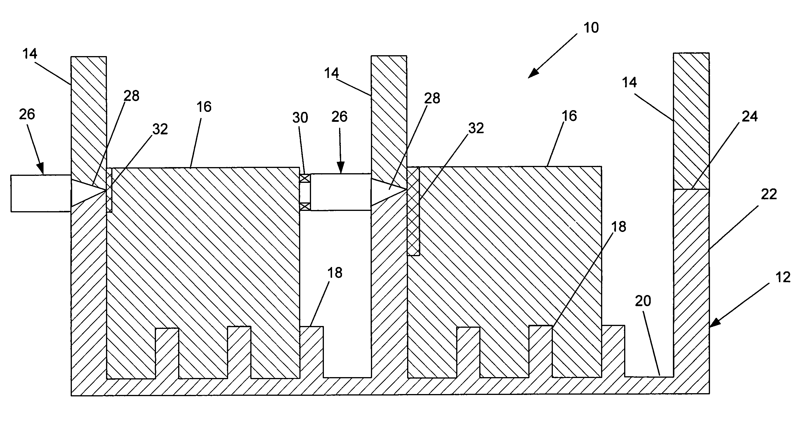
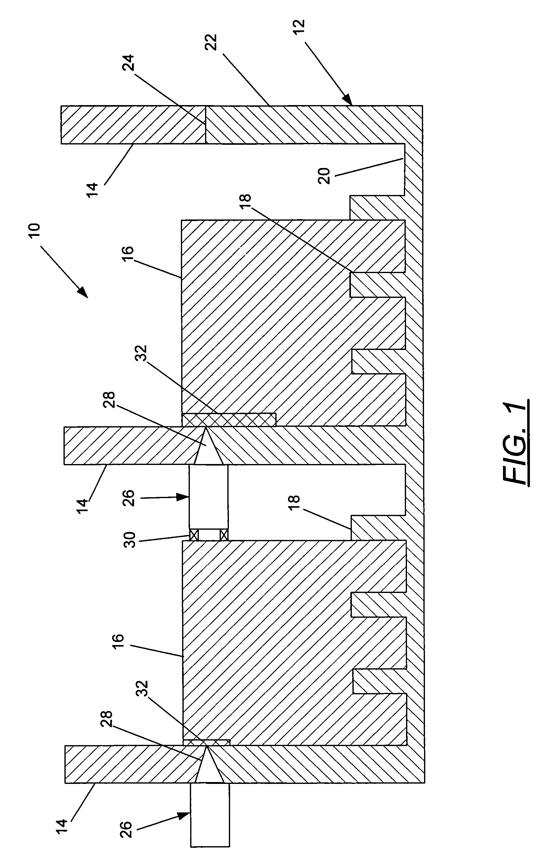
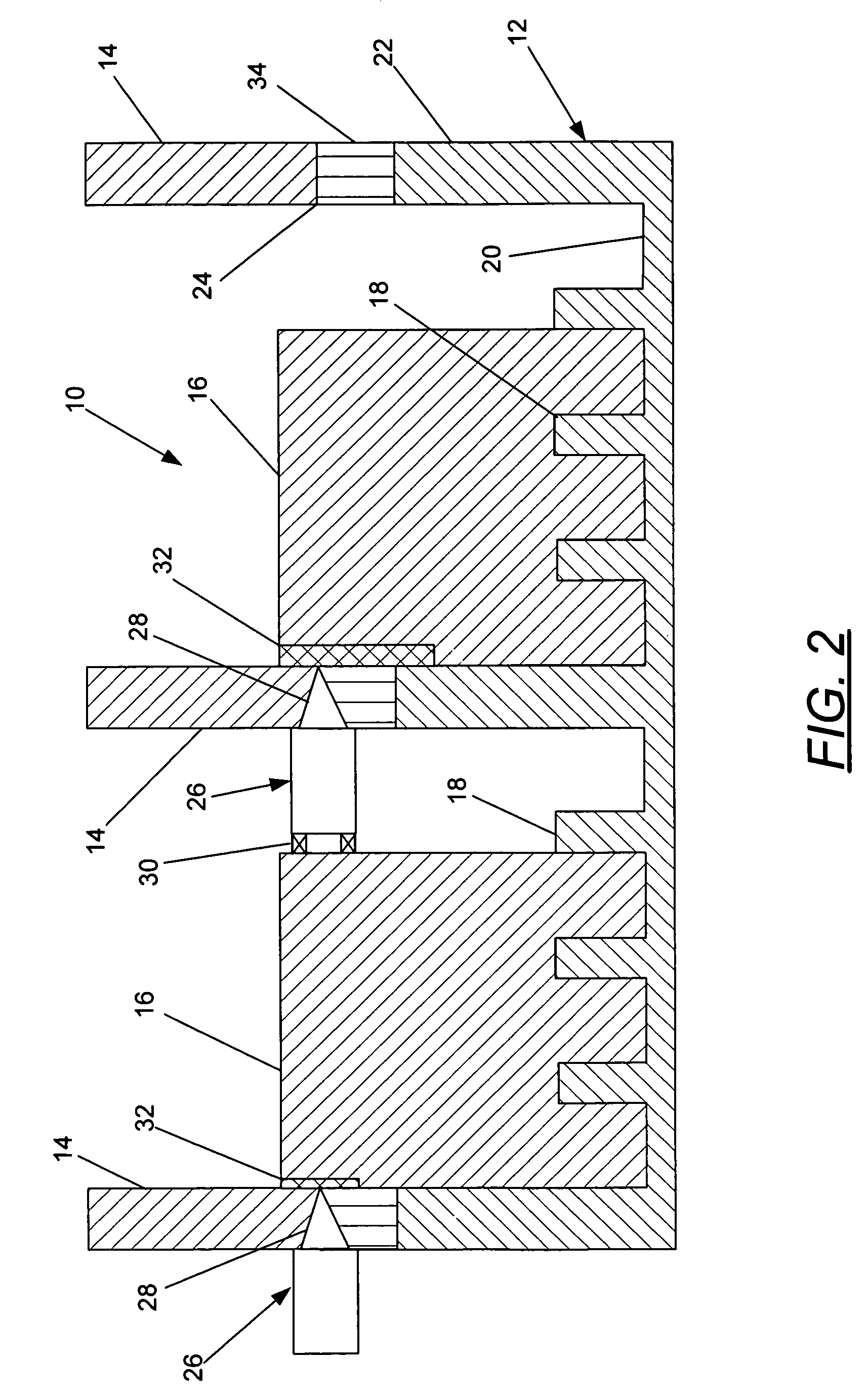
[0023]Referring now to the drawings and, in particular to FIG. 1 there is shown a structural assembly 10 that is capable of being friction stir welded into a unitized friction stir welded structure. The structural assembly 10 includes an engaging structure 12 and substructure 14 arranged to be friction stir welded together. A tooling block 16 is positioned to engage the engaging structure 12 and to support the engaging structure and substructure 14 during friction stir welding such that a butt joint may be formed ...


PUM

PropertyMeasurementUnit
angleaaaaaaaaaa
stress concentrationsaaaaaaaaaa
frictionaaaaaaaaaa

Abstract

An assembly for positioning a structural assembly for friction stir welding, and a system and method for friction stir welding the structural assembly are provided. The assembly includes an engaging structure and at least one tooling block capable of engaging the engaging structure, as well as a substructure positioned adjacent to the engaging structure and tooling block. The substructure and engaging structure capable of being friction stir welded together to form a butt joint therebetween.

Description

BACKGROUND OF THE INVENTION[0001]1) Field of the Invention[0002]The present invention relates to friction stir welding and, more particularly, to positioning a structural assembly for friction stir welding, and friction stir welding the structural assembly to form a unitized friction stir welded structure.[0003]2) Description of Related Art[0004]Friction stir welding is a process in which a rotating tool, such as a pin or probe, is urged into and / or through a workpiece, e.g., to join multiple members of the workpiece in a solid state or to repair cracks in a workpiece. Typically, the pin extends from a shoulder, which can be flat, concave, or otherwise contoured, and the shoulder is urged against the workpiece so that the pin is urged therein. The pin is then urged through the workpiece to form a continuous weld joint. For example, during one conventional friction stir welding process, the probe of the rotating tool is plunged into a workpiece or between two workpieces by a friction...

Claims


Application Information

Patent Timeline
Patent Type & Authority Patents(United States)
IPC IPC(8): B23K20/12B23K37/04
CPCB23K20/126
Inventor SLATTERY, KEVIN T.
Owner THE BOEING CO
Features
  • R&D
  • Intellectual Property
  • Life Sciences
  • Materials
  • Tech Scout
  • Unparalleled Data Quality
  • Higher Quality Content
  • 60% Fewer Hallucinations
Learn More