X-ray CT scanner and scan method

a ct scanner and x-ray technology, applied in tomography, instruments, applications, etc., can solve the problems of inability to use ct scanners, inability to adopt ct scans of people practically, and inability to change the field of view of ct scans (or the size of a region of interest) more easily

Active Publication Date: 2008-03-25
MORITA MFG CO LTD
View PDF2 Cites 26 Cited by
  • Summary
  • Abstract
  • Description
  • Claims
  • Application Information

AI Technical Summary

Benefits of technology

[0005]An object of the invention is to change a field of view of CT scan (or a size of a region of interest) more easily.

Problems solved by technology

When the object is a person, problems such as artifacts due to his or her motions and dizziness caused by the rotation occur.
Therefore, it cannot be adopted practically for CT scan of a person, especially for medical areas.
Further, even when the object is a matter, the CT scanner cannot be used if the object has a structure so precise as not to be subjected to continuous rotation.

Method used


Image

  • X-ray CT scanner and scan method
  • X-ray CT scanner and scan method
  • X-ray CT scanner and scan method

Examples


Embodiment Construction

[0037]Embodiments of the invention are explained below with reference to the appended drawings, wherein like reference characters designate like or corresponding parts throughout the several views.

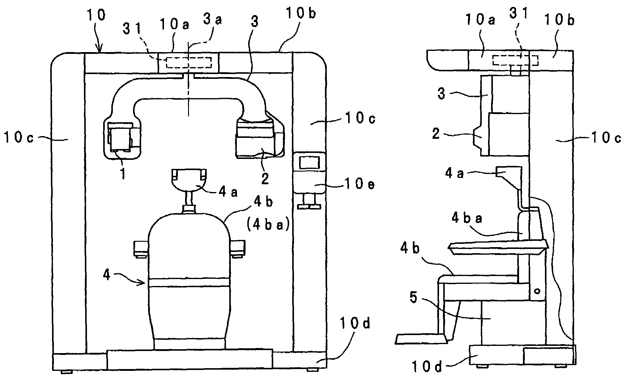
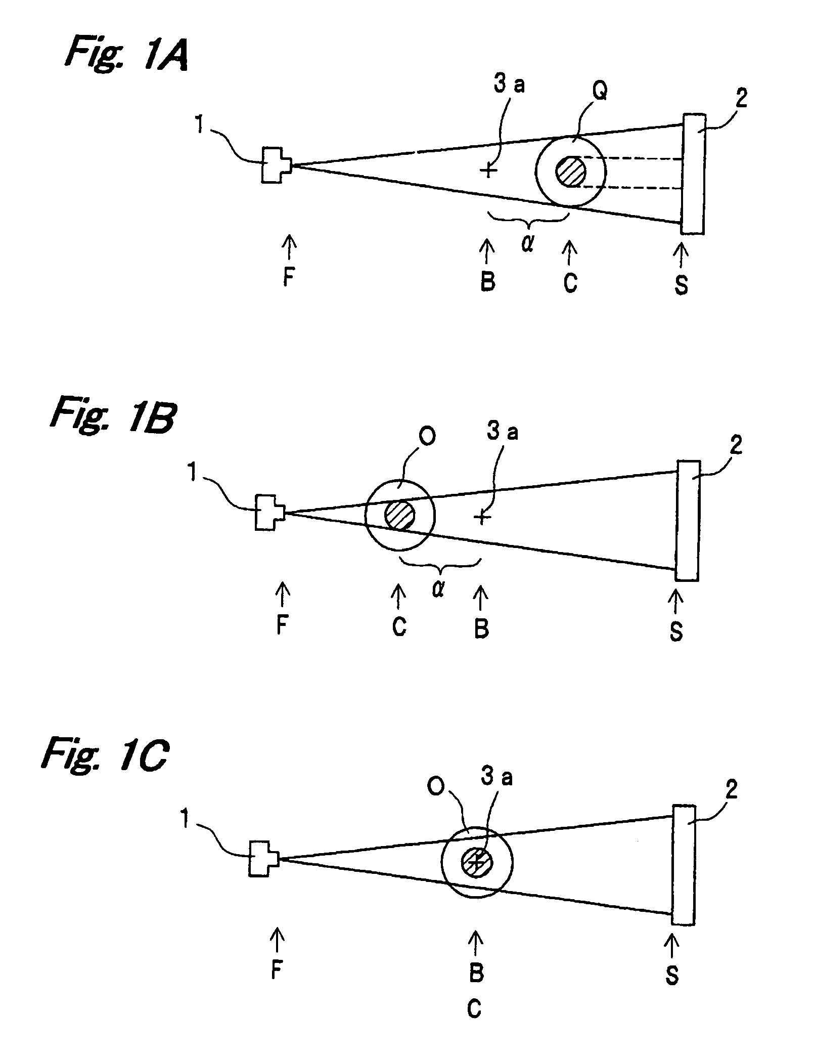
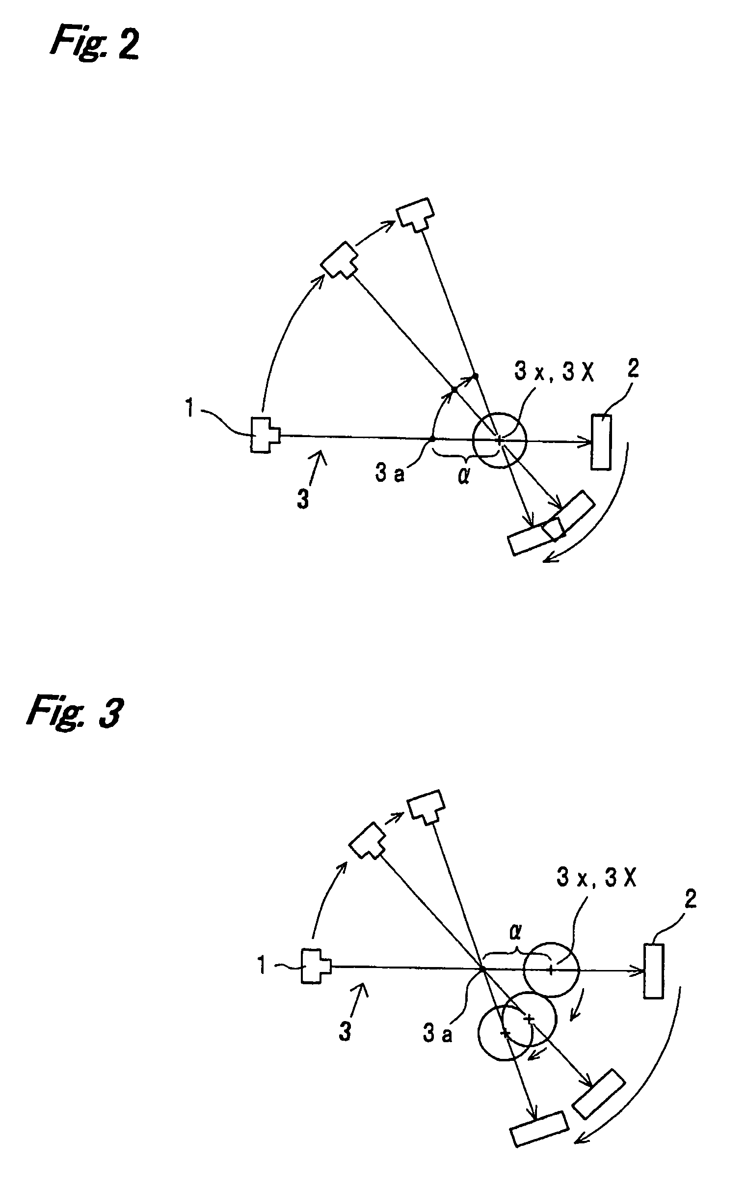
[0038]In an X-ray CT scanner, a rotary device such as a rotary arm has an X-ray generator 1 and an X-ray detector 2 opposing to each other while interposing an object between them. The distance between the X-ray generator 1 and the X-ray detector 2 is constant. A rotary mechanism supports the rotary device so as to be rotatable around a rotary axis in the rotary mechanism. The rotary axis is referred to as “mechanical rotary axis” or simply as “rotary axis”. The mechanical rotary axis or rotary axis can be set, for example, by use of a rotary shaft because a rotary shaft having the rotary axis is used for rotation by the rotary mechanism. Any rotary mechanism can be used to rotate at least an X-ray generator 1 and an X-ray detector 2. Even if the rotary mechanism has no mechanical shaft, i...


PUM


Abstract

In an X-ray CT scan, a distance between an X-ray generator and a rotation center and / or a distance between a X-ray detector and the rotation center can be changed according to a magnification of an image. A rotary device has an X-ray generator and an X-ray detector opposing to each other, provided to interpose an object between them. A rotary mechanism rotates the rotary device around a rotary axis, and a movement mechanism moves the rotary axis or the object in a plane perpendicular to the rotary axis. The rotation center in a viewpoint of CT scan different from the rotary axis is always kept at a point in a region of interest in the object according to a motion synthesized from the rotation of the rotary device and the movement of the rotary axis or the object.

Description

FIELD OF THE INVENTION[0001]The invention relates to X-ray computer tomography for reconstructing an image in a three-dimensional region.BACKGROUND ART[0002]In an X-ray computer tomography (CT) scanner, an object is positioned between an X-ray generator and an X-ray detector. The X-ray generator and the X-ray detector are rotated around the object, and the object is exposed to an X-ray beam generated by the X-ray generator beam in many directions. The X-ray intensity distribution transmitting the object (or a projection of the object) is measured with the X-ray detector. Based on the X-ray projection data acquired in one rotation, a distribution of linear absorption coefficients (or an image) inside the object is reconstructed two-dimensionally to create a slice image of the object. The reconstruction calculation is performed on a plurality of planes perpendicular to the rotary axis, to create a three-dimensional image based on the slice images.[0003]If a magnification of an image c...

Claims


Application Information

Patent Timeline
Patent Type & Authority Patents(United States)
IPC IPC(8): H05G1/02
CPCA61B6/589A61B6/032A61B6/14
Inventor SADAKANE, TOMOYUKISUZUKI
Owner MORITA MFG CO LTD
Why Eureka
Try Eureka