Connector

a technology of connecting rods and contacts, applied in the direction of coupling contact members, coupling device connections, coupling contact members, etc., can solve the problems of increased production costs, and achieve the effect of smooth and ensured operation

Active Publication Date: 2008-03-25
YAZAKI CORP
View PDF3 Cites 9 Cited by
  • Summary
  • Abstract
  • Description
  • Claims
  • Application Information

AI Technical Summary

Benefits of technology

[0011]The invention was made in view of these situations, and an object thereof is to provide a connector which enables the cancellation of locking of the retainer by the retainer operating jig, obviates the necessity of operating the retainer operating jig more than required so as to prevent the failure or the like of the connector housing and the locking mechanism of the retainer, and furthermore, enables a smooth and ensured operation by the retainer operating jig without requiring a special construction and configuration for the retainer operating jig.
[0016]2) The retainer may include a temporary locking retainer side tapered portion which enables the retainer to be displaced from the proper locking position to the temporary locking position when the retainer operating jig is inserted.
[0017]According to the connector that is configured as has been described above, when operating to displace the retain from the proper locking position to the temporary locking position, the retainer operating jig is inserted from the temporary locking jig inserting hole in the connector housing. In association with the inserting operation of the retainer operating jig, the retainer which is being situated in the proper locking position is displaced to the temporary locking position. Consequently, the cancellation of locking of the retainer by the retainer operating jig can easily be implemented, and the retainer can be displaced from the proper locking position to the temporary locking position smoothly and in an ensured fashion without operating the retainer operating jig more than required.
[0018]In addition, since the retainer includes the temporary locking retainer side tapered portion, the retainer operating jig is brought into sliding contact with the temporary locking retainer side tapered portion, thereby making it possible to implement the displacement of the retainer from the proper locking position to the temporary locking position in the simple configuration and in an ensured fashion.
[0020]According to the connector that is configured as has been described above, when operating to displace the retainer from the temporary locking position to the proper locking position, the retainer operating jig is inserted from the proper locking jig inserting hole in the connector housing. In association with the inserting operation of the retainer operating jig, the retainer operating jig is brought into sliding contact with the proper locking retainer side tapered portion on the retainer, whereby the retainer which is being situated in the temporary locking position is displaced to the proper locking position. Consequently, the displacement of the retainer from the proper locking position to the temporary locking position and the displacement of the retainer from the temporary locking position to the proper locking position by the retainer operating jig can easily be implemented.
[0021]According to the connector of the invention, there are obtained advantages that the cancellation of locking of the retainer by the retainer operating jig can be enabled, that the necessity of operating the retainer operating jig more than required is obviated, so as to prevent the failure or the like of the connector housing and the locking mechanism of the retainer, and furthermore that a smooth and ensured operation by the retainer operating jig can be implemented without requiring a special construction and configuration for the retainer operating jig.

Problems solved by technology

Because of this, in order to perform a smooth and ensured operation, the construction and configuration of the retainer operating jig 130 need to be special, leading to a problem that the production costs are increased.

Method used


Image

  • Connector
  • Connector
  • Connector

Examples


Embodiment Construction

[0029]Hereinafter, the invention will be described by reference to an embodiment which is illustrated in the accompanying drawings.

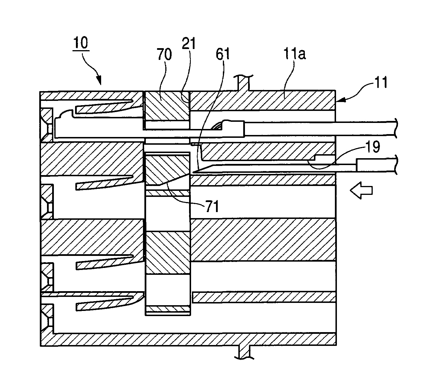
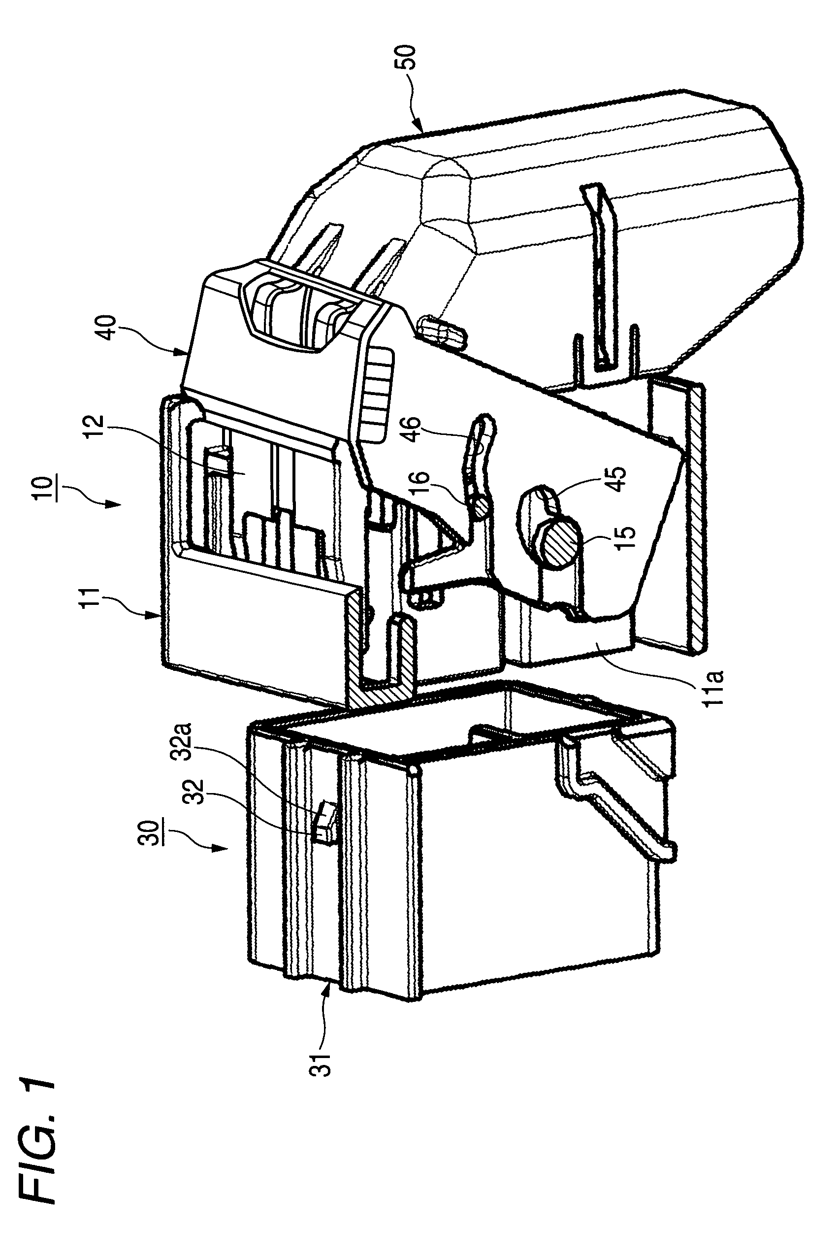
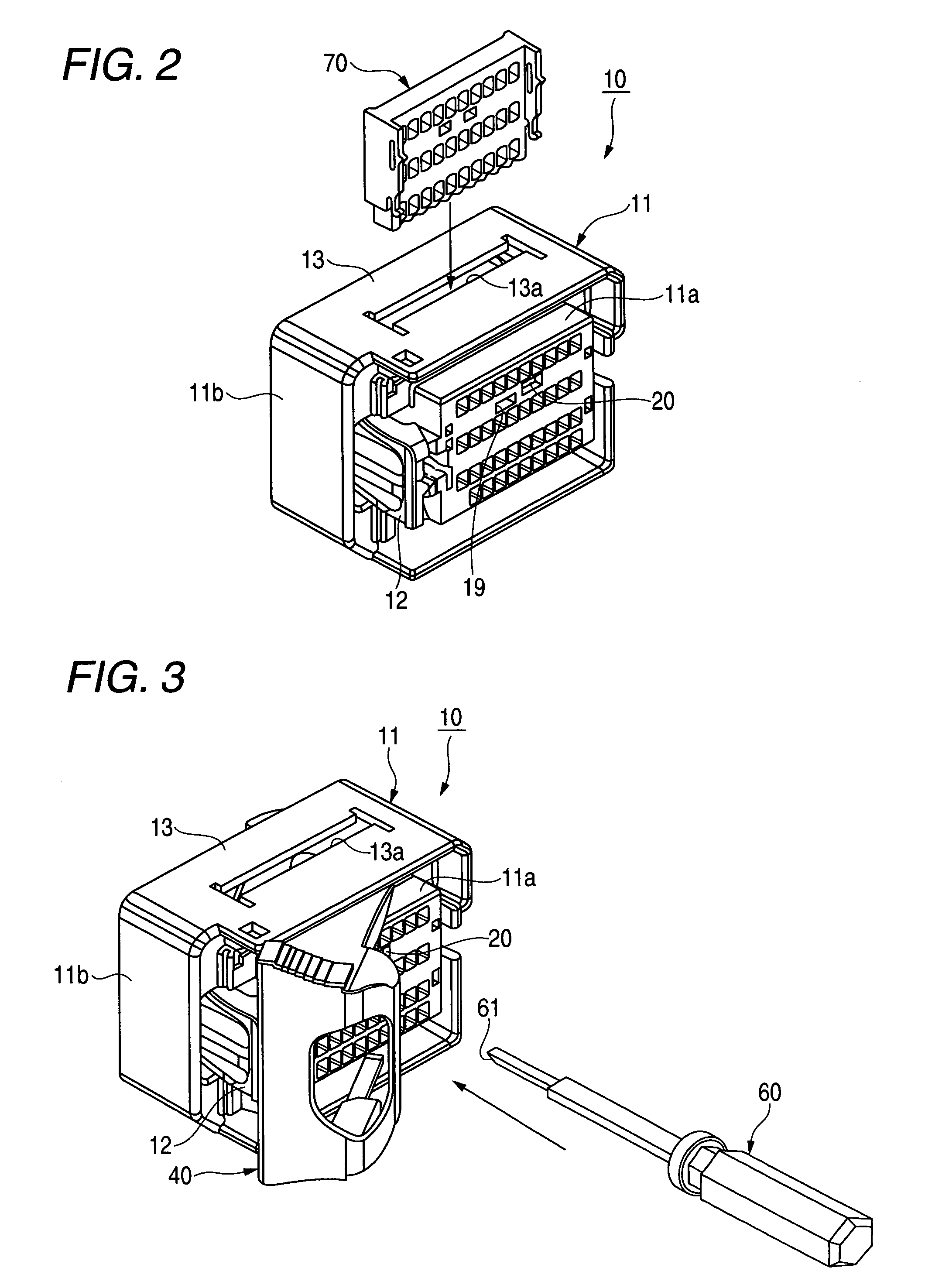
[0030]FIG. 1 is a perspective view of a connector of an embodiment of the invention with part of an outer housing removed therefrom which shows a state resulting before connectors are fitted together, FIG. 2 is a perspective view showing the state in FIG. 1 in which a retainer has not yet been assembled, FIG. 3 is a perspective view showing the state in FIG. 1 in which the retainer and a lever have been assembled with the lever located in a temporary locking position, and FIG. 4 is a sectional view of a main part of FIG. 1. In addition, FIGS. 5A and 5B show schematic sectional views of the main part of the connector in FIG. 1 which show the periphery of a temporary locking jig inserting hole for explanation of a displacing operation of a retainer from a proper locking position to a temporary locking portion by a retainer operating jig, in which FIG. 5A s...


PUM


Abstract

A temporary locking jig inserting hole which enables a retainer operating jig to be inserted thereinto from the outside is provided on a side of an inner housing of a female connector from which electric wires are drawn out in such a manner as to extend along a direction in which female terminals are inserted into the inner housing. In addition, a temporary locking retainer side tapered portion is provided on a retainer in such a manner as to correspond in position to the temporary locking jig inserting hole. In association with the insertion of the retainer operating jig from the temporary locking jig inserting hole, the temporary locking retainer side tapered portion is brought into sliding contact with a jig side tapered portion of the retainer operating jig, so as to displace the retainer which is being in a proper locking position to a temporary locking position.

Description

BACKGROUND OF THE INVENTION[0001]1. Field of the Invention[0002]The present invention relates to a connector in which a terminal inserted into a connector housing is locked by a retainer.[0003]2. Related Art[0004]Conventionally, connectors have been known (refer to, for example, JP-A-2003-51352). FIG. 7 is a sectional view which shows a connector and a retainer operating jig which are disclosed in JP-A-2003-51352.[0005]Referring to FIG. 7, in a connector, a retainer inserting opening 101 is provided in a female housing 100 in a direction (in FIG. 7, in a vertical direction) which intersects an inserting direction (in the figure, in a horizontal direction) of a female side terminal metallic fixture 110 at substantially right angles, and a retainer 120 is inserted from the relevant direction.[0006]A jig inserting opening 102 is provided in an edge portion of the retainer inserting opening 101 along an inclined direction in such a manner as to communicate with an engagement hole 121 pr...

Claims


Application Information

Patent Timeline
Patent Type & Authority Patents(United States)
IPC IPC(8): H01R13/40
CPCH01R13/4362H01R13/62938H01R43/22
Inventor OHTAKA, KAZUTOTAKAHASHI, TOSHIHARU
Owner YAZAKI CORP
Why Eureka
Try Eureka