Electricity-inducing immobilization cartridge attachment

a cartridge and immobilization technology, applied in the field of contact mechanisms, can solve the problems of reducing the chance and reducing the chance of lethal injury to the target. the effect of ensuring the penetration of the target, reducing the chance of injury to the target person or animal, and spreading the for

Inactive Publication Date: 2008-04-01
HENDRIX GLEN
View PDF7 Cites 4 Cited by
  • Summary
  • Abstract
  • Description
  • Claims
  • Application Information

AI Technical Summary

Benefits of technology

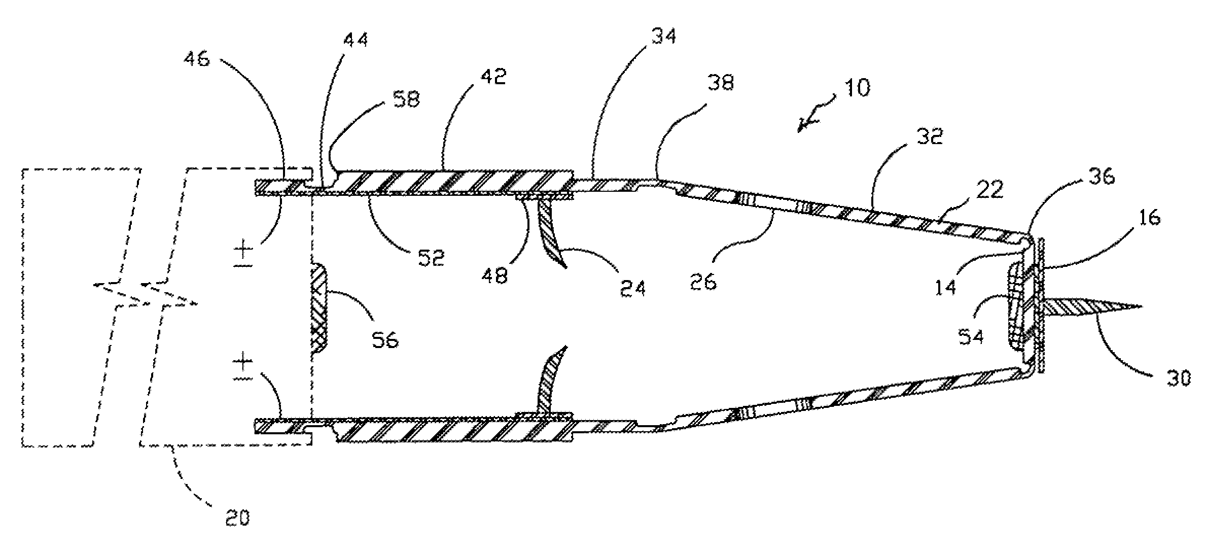
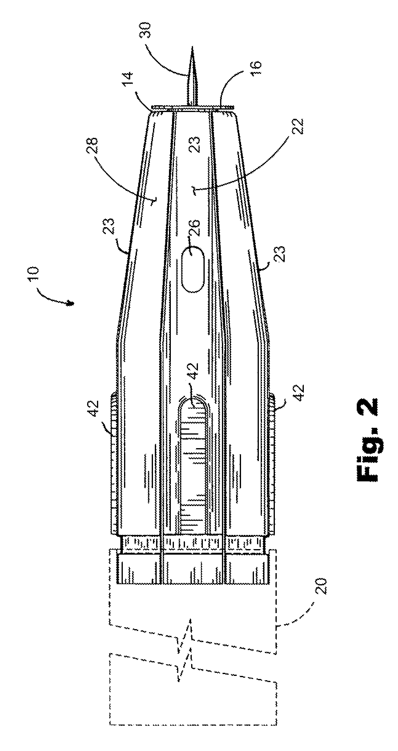
[0022]The optimal number of converging sections is eight, but more or less may be employed. The use of eight such sections is large enough to be structurally sound, while small enough to allow a proper radial diameter when attaching to the cartridge. The barb is a curved barb that is attached to the interior of alternate sections so as to point inwardly. The barb is located on the portion of the section hingedly connected to the cartridge near the middle hinge and is electrically contiguous with a conducting lead such as tape, wire or an otherwise disposed conducting material, which runs from the barb to an electrical contact on the cartridge. A hole is located on the portion of the section hingedly connected to the front strike plate the same distance from the middle hinge as the curved barb. The rear portion of these barb segments has a raised thicker portion down the center. The end of this stiffener toward the cartridge seats onto a ledge on the cartridge when the device folds up upon contact with the target. This helps to transmit the force of the cartridge to the barb so as to give greater assurance of the barb penetrating the target.
[0023]The hook-and-loop material is formed on the sections between the barbed sections. The sections attach to the cartridge in a slightly arcing manner. They are forced into an arc-shaped slot in the cartridge which stiffen these segments so as to allow the entire device to maintain its shape despite wind pressure, any centripetal forces and acceleration upon firing the cartridge. The hinge at this juncture is also curved and tears from the edges toward the center of the segment when the device folds up. This design feature assures that the device of the present invention can only be used once, even during target practice.
[0024]In practice, the attachment of the present invention is secured to the front of the cartridge. The attachment will fold up upon striking a target. The barb on the strike plate affixes the device to the target. The individual sections fold into a flat, circular plane against the target. This circular area has a greater diameter than that of the cartridge, and thus, spreads the force of the impact over a greater area. This lessens the chance of injury to the targeted person or animal. The barbs will protrude through the corresponding holes and affix to the target. The barbs are curved, or angled, so that they are more or less parallel to the trajectory of the tip of the barb at the point of impact. This allows the barb to penetrate the skin and flesh of the target with as little physical damage as possible. When a pair of opposing barbs penetrate at this angle and are locked in place by the hook-and-loop material, it makes it less likely for the device to be dislodged for any reason.
[0025]The attachment of the present invention is sized so that opposing barbs or sections are four inches or more apart after impact. This is a sufficient distance for an effective current to travel through the intended target. The hook-and-loop material on the sections, along with the hook-and-loop material on the strike plate, will be forced together so as to lock the barbs in the protruding condition and to keep the attachment, and associated cartridge, from bouncing off the target upon impact. After the central spike has penetrated the target and the front strike plate is in contact with the target, but before the segments have folded, a TEFLON (TM) washer surrounds the spike so as to serve as a rotating slide plate to reduce the torque delivered to the rest of the device. This prevents warpage and possible misalignment of the barbs with their respective openings.

Problems solved by technology

There are disadvantages to the taser system.
An officer may have to fall back on lethal means to protect himself or others.
Worse, a citizen using a taser for home defense may find him or herself at the mercy of a criminal should the one shot fail.
This cartridge would increase the popularity of the weapon, but it raises other problems.
Unfortunately, diameters of less than two inches presents another problem.
The mass of the cartridge presents yet another problem.
The currently used darts do not have enough mass to pull the barb shaft loose upon rebound from the surface of the target.
A cartridge with a mass of two to four ounces will have this problem.
This solution appears to be cumbersome.
However, if the cartridge strikes the body at an outer periphery, the secondary dart could miss altogether.
Although sufficient distance between contact points can be obtained with this device, it does not address the problem of the impact of the cartridge.

Method used


Image

  • Electricity-inducing immobilization cartridge attachment
  • Electricity-inducing immobilization cartridge attachment
  • Electricity-inducing immobilization cartridge attachment

Examples


Embodiment Construction

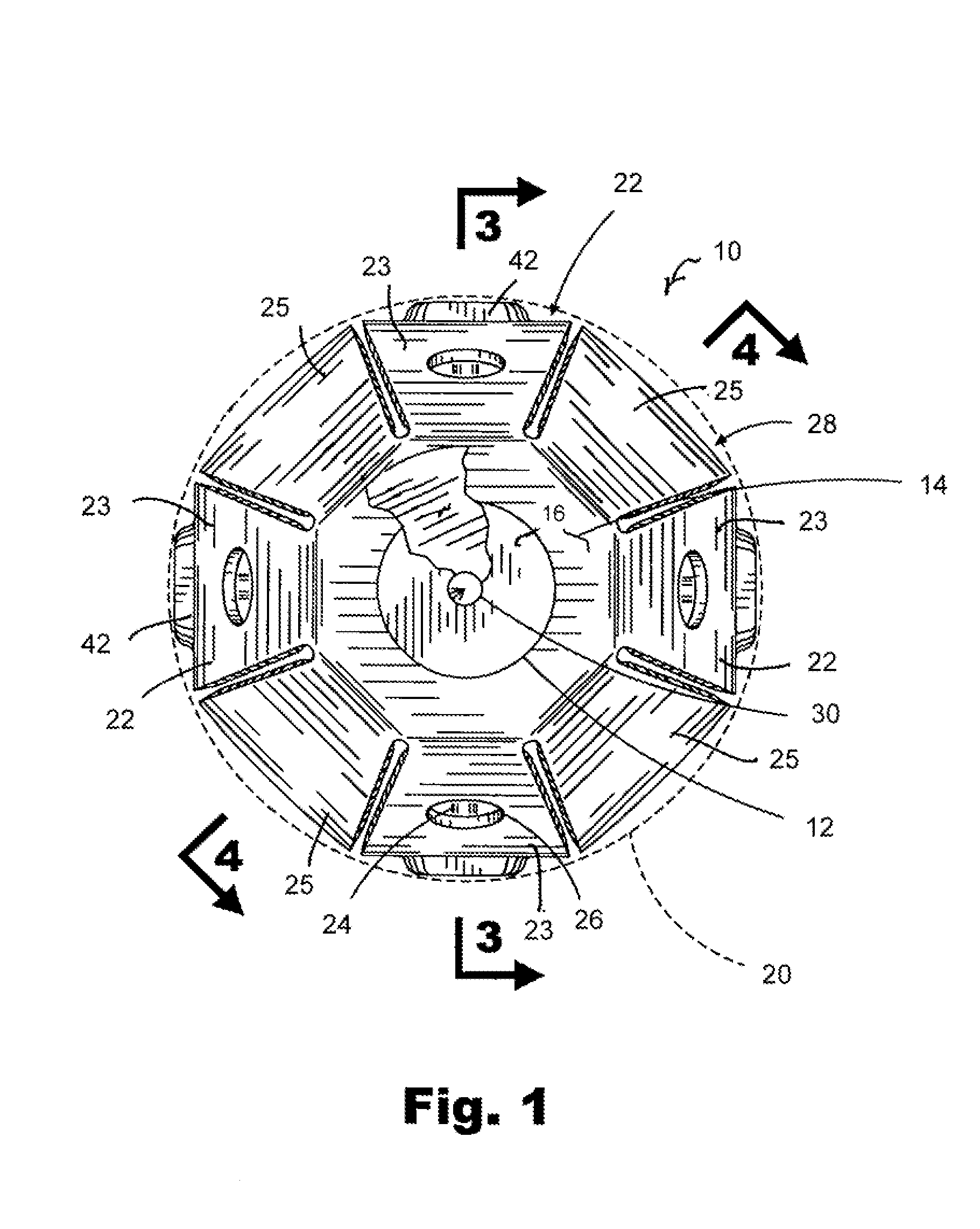
[0037]Referring to FIG. 1, there is shown the attachment 10 of the present invention that can be secured to an electricity-inducing immobilization cartridge. The illustration of FIG. 1 shows the device 10 in its configuration from the target's point of view. In FIG. 1, it can be seen that the attachment 10 includes eight sections 22. These sections 22 alternate between sections 23 which support the barb and sections 25 which support the hook-and-loop material. Sections 23 and 25 alternate around the periphery of the attachment 10. The sections 23 have a barb 24 (partially illustrated) and a hole 26. A reinforcement 42 is illustrated on sections 23.

[0038]In FIG. 1, it can be seen that there is a spike 30 supported on a mounting base 12. The spike 30, along with the mounting base 12 are adhered to a strike plate 14. A teflon washer 16 slides over the spike 30 and rests against the mounting base 12. This teflon washer 16 has a tight running fit on the spike 30. In other words, the wash...


PUM


Abstract

An attachment to an electricity-inducing immobilization cartridge has a body with a plurality of converging sections, a strike plate affixed at a front end of the body and a plurality of hinges formed on each of the converging sections. The hinges serve to allow the plurality of converging sections to fold when the strike plate contacts a target. A barb is affixed to an inner surface of at least one of the sections so as to be movable from the interior of the body to a location exterior of the body when the strike plate contacts the target. Fasteners are provided within the body so as to maintain the body in a collapsed condition subsequent to the strike plate contacting the target.

Description

RELATED U.S. APPLICATIONS[0001]Not applicable.STATEMENT REGARDING FEDERALLY SPONSORED RESEARCH OR DEVELOPMENT[0002]Not applicable.REFERENCE TO MICROFICHE APPENDIX[0003]Not applicable.FIELD OF THE INVENTION[0004]The present invention relates generally to the field of non-lethal weapons for immobilizing a live target. More particularly, the present invention is directed to a contact mechanism which allows the electrical charge from the cartridge to be delivered from the target in a safe and effective manner.BACKGROUND OF THE INVENTION[0005]Taser and taser-type products have been around for decades. The taser weapon operates by projecting two darts trailing conductive wires. There are disadvantages to the taser system. The optimal distances required for successful use of the weapon are between 3 and 21 feet. Less than 3 feet, the darts are too close together to properly conduct electricity. Beyond 21 feet, the darts are too far apart for both of them to strike the target. The electrica...

Claims


Application Information

Patent Timeline
Patent Type & Authority Patents(United States)
IPC IPC(8): F42B30/00
CPCF41H13/0031F42B12/36
Inventor HENDRIX, GLEN
Owner HENDRIX GLEN
Why Eureka
Try Eureka