Method and apparatus for measuring a depth of holes in composite-material workpieces being machined by an orbiting cutting tool

a technology of composite materials and cutting tools, which is applied in the direction of electrical apparatus, electrical/magnetic measuring arrangements, printed circuit manufacturing, etc., can solve the problems of affecting the accuracy of the measurement, so as to achieve the effect of reducing the axial movement of the cutting tool

Inactive Publication Date: 2008-04-01
NOVATOR
View PDF20 Cites 9 Cited by
  • Summary
  • Abstract
  • Description
  • Claims
  • Application Information

AI Technical Summary

Benefits of technology

[0023]Furthermore, owing to the present method of sensing the exact position where the cutting head has fully penetrated the workpiece, it is also possible to minimize the axial movement of the cutting tool in order to avoid unnecessary drilling in the air of the cutting tool after the penetration of the workpiece.

Problems solved by technology

However, such measuring methods are sensitive to disturbances and interferences caused by and transferred from mechanical working operations being performed simultaneously on other locations of the same workpiece.
This may jeopardize the reliability of the measuring results of the depth in the respective hole.

Method used


Image

  • Method and apparatus for measuring a depth of holes in composite-material workpieces being machined by an orbiting cutting tool
  • Method and apparatus for measuring a depth of holes in composite-material workpieces being machined by an orbiting cutting tool
  • Method and apparatus for measuring a depth of holes in composite-material workpieces being machined by an orbiting cutting tool

Examples


Embodiment Construction

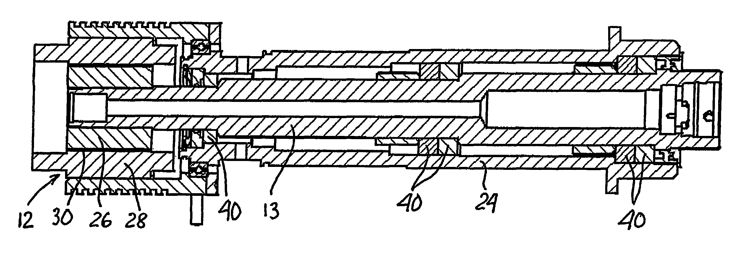
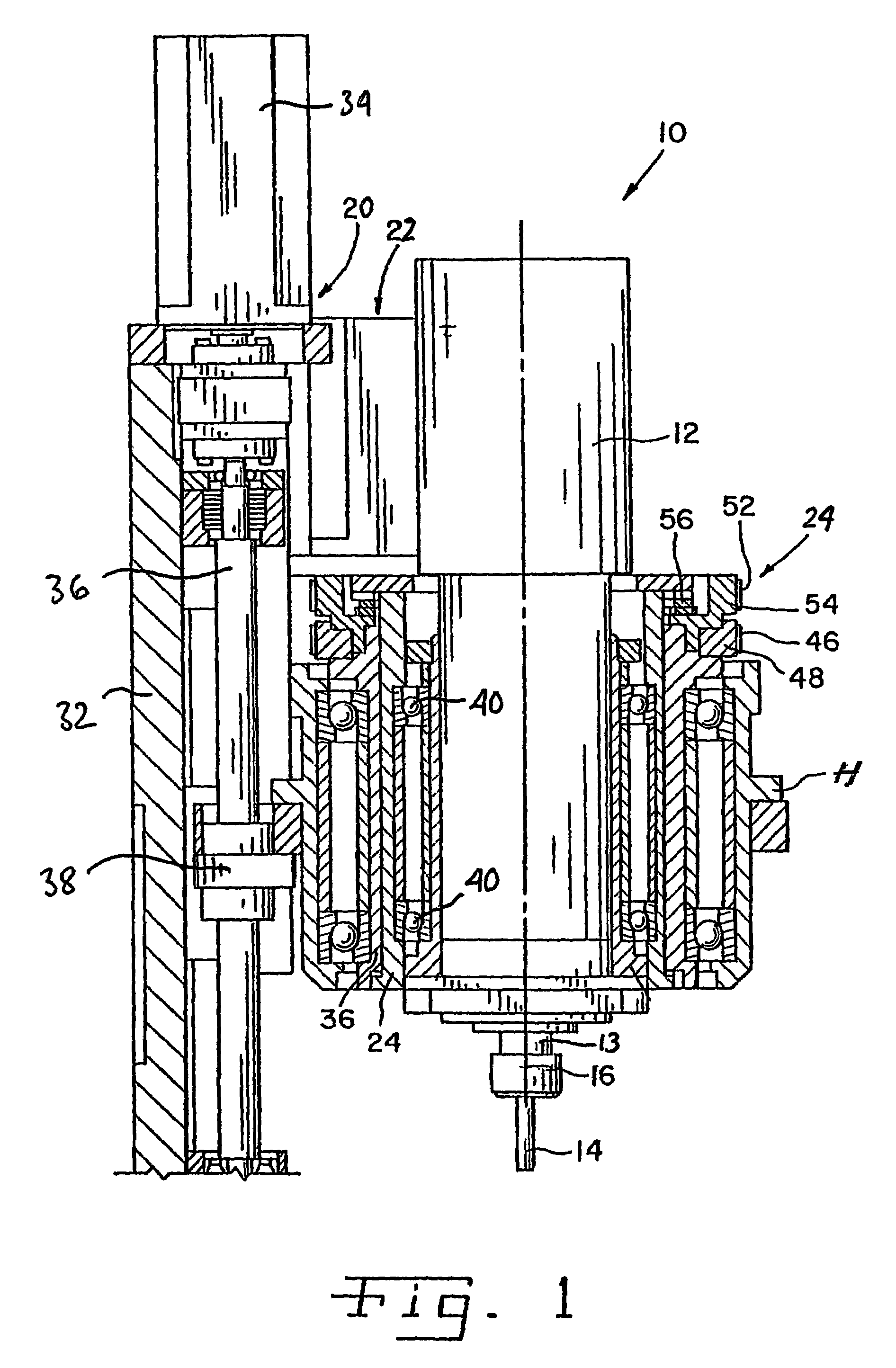
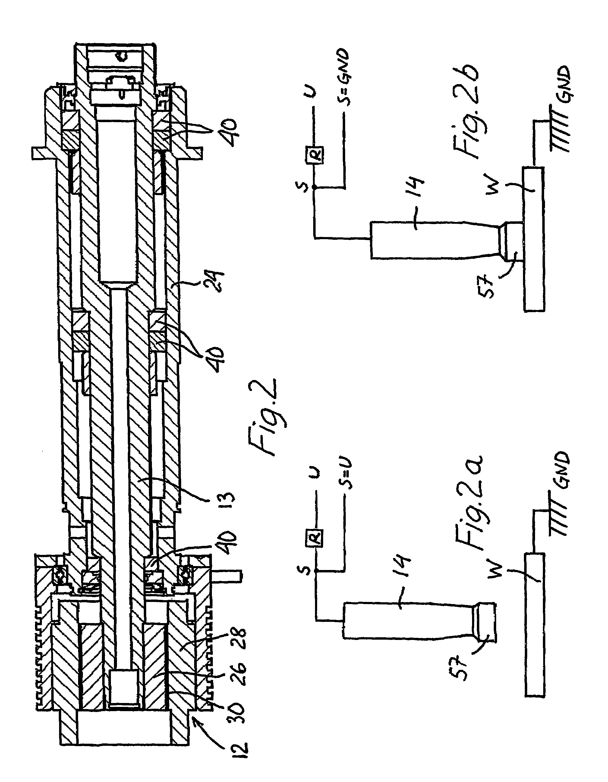
[0034]Referring now to the drawings, and more particularly to FIG. 1, in the method of the present invention for measuring the depth of a hole being machined in a composite-material workpiece an orbital machining apparatus 10 is used. Orbital machining apparatus 10 includes at least some of, and / or similar, elements such as described in e.g. WO 01 / 15870 A2, WO 03 / 008136 A1, U.S. Pat. No. 5,971,678, incorporated herein by reference. A first actuator in a form of a spindle motor unit 12 is configured for rotating a spindle 13 and a cutting tool 14 having a longitudinal center axis 16 during the machining of the hole; a second actuator 20 configured for moving cutting tool 14 in an axial feed direction towards and into the workpiece substantially parallel to tool axis 16, the second actuator 20 being simultaneously operable with first actuator 12. A third actuator 22 is configured for rotating cutting tool 14 about a principal axis, the principal axis being substantially parallel to ce...


PUM

PropertyMeasurementUnit
depthaaaaaaaaaa
electric potentialaaaaaaaaaa
axial lengthaaaaaaaaaa

Abstract

A method and apparatus for measuring a hole depth in a composite-material workpiece machined by a orbital cutting tool, including the steps of applying a low-level electric potential to an electrically insulated cutting tool having a cutting head with radial and axial cutting edges and with a predetermined axial length; determining a first zero reference position as the cutting tool initially contacts a first surface of the workpiece and closes an electric circuit through the grounded workpiece; and detecting a second reference position when the cutting head penetrates an opposite, second surface of the workpiece. The finished hole depth is determined by deducting the predetermined axial length of the cutting head from the total length of axial advancement from the first zero reference position to the second reference position. The orbital machining apparatus includes ceramic bearings electrically insulating the spindle and the cutting tool from surrounding components of the apparatus.

Description

BACKGROUND OF THE INVENTION[0001]1. Field of the Invention[0002]The present invention relates to a method and an apparatus for measuring a depth of a hole in a composite-material workpiece machined by a rotating cutting tool orbiting about a principal axis. The present invention is, in particular, useful when making holes in multilayered workpieces, for example in various fiber-reinforced composite materials, laminates or material stacks including at least two layers material for use in the aircraft and space technologies.[0003]2. Description of the Related Art[0004]In aircraft multilayered components the thickness thereof may vary along the extent of the workpiece and thus the depth of the holes being formed therein may vary accordingly. It is important to accurately determine the individual depth of each hole being formed so as to be able to properly match the hole with an individual, accurately fitting fastener, such as a bolt or a blind fastener. Also, it is desirable to minimiz...

Claims


Application Information

Patent Timeline
Patent Type & Authority Patents(United States)
IPC IPC(8): B23B49/00B23C1/00G01B7/06B23B35/00B23Q17/20B23Q17/22
CPCB23B35/00B23Q17/20B23Q17/22B23Q17/2233Y10T408/65B23B2226/27B23B2228/36B23B2260/128B23C2226/27B23C2270/022Y10T409/303752Y10T409/306944Y10T409/307616Y10T409/307056Y10T408/03B23B2215/04B23Q17/2241B23C2220/52
Inventor ODEN, ERIKPETTERSSON, BJORN
Owner NOVATOR
Why Eureka
Try Eureka