Method and apparatus for cystocele repair

a cystocele and cystocele technology, applied in the field of cystocele repair, can solve the problems of increasing abdominal pressure, increasing the risk of genital prolapse, and long-standing genital prolapse of women, and achieve the effect of reducing the bulge of the bladder into the vagina of the patien

Active Publication Date: 2008-04-01
ASTORA WOMENS HEALTH
View PDF205 Cites 251 Cited by
  • Summary
  • Abstract
  • Description
  • Claims
  • Application Information

AI Technical Summary

Problems solved by technology

Female genital prolapse has long plagued women.
With the increasing age of the U.S. population, these problems will likely assume additional importance.
Increases in abdominal pressure, failure of the muscles to keep the pelvic floor closed, and damage to the ligaments and fasciae all contribute to the development of prolapse.
Vaginal pessaries are the primary type of nonsurgical treatment, but there can be complications due to vaginal wall ulceration.

Method used


Image

  • Method and apparatus for cystocele repair
  • Method and apparatus for cystocele repair
  • Method and apparatus for cystocele repair

Examples


first embodiment

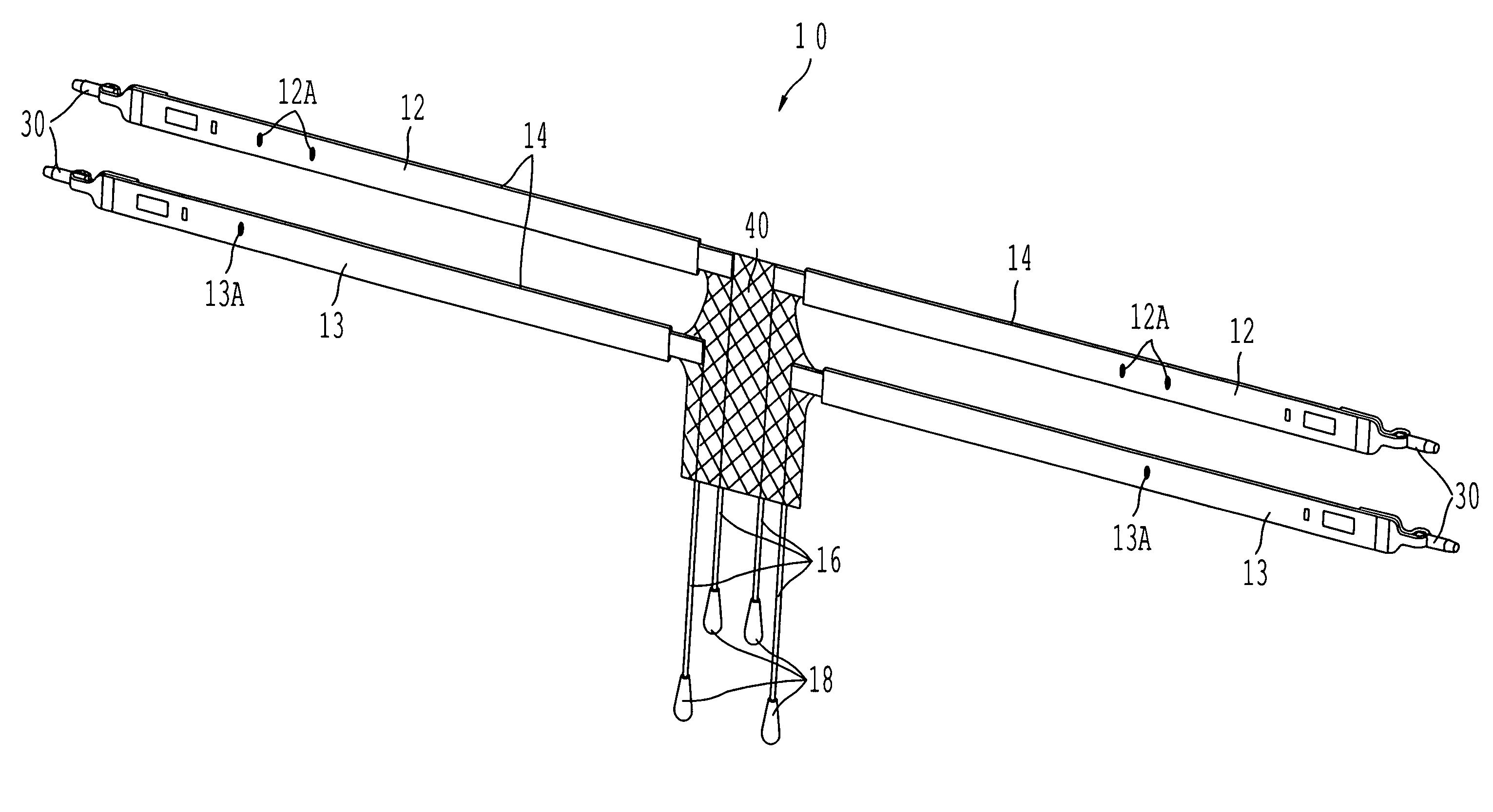
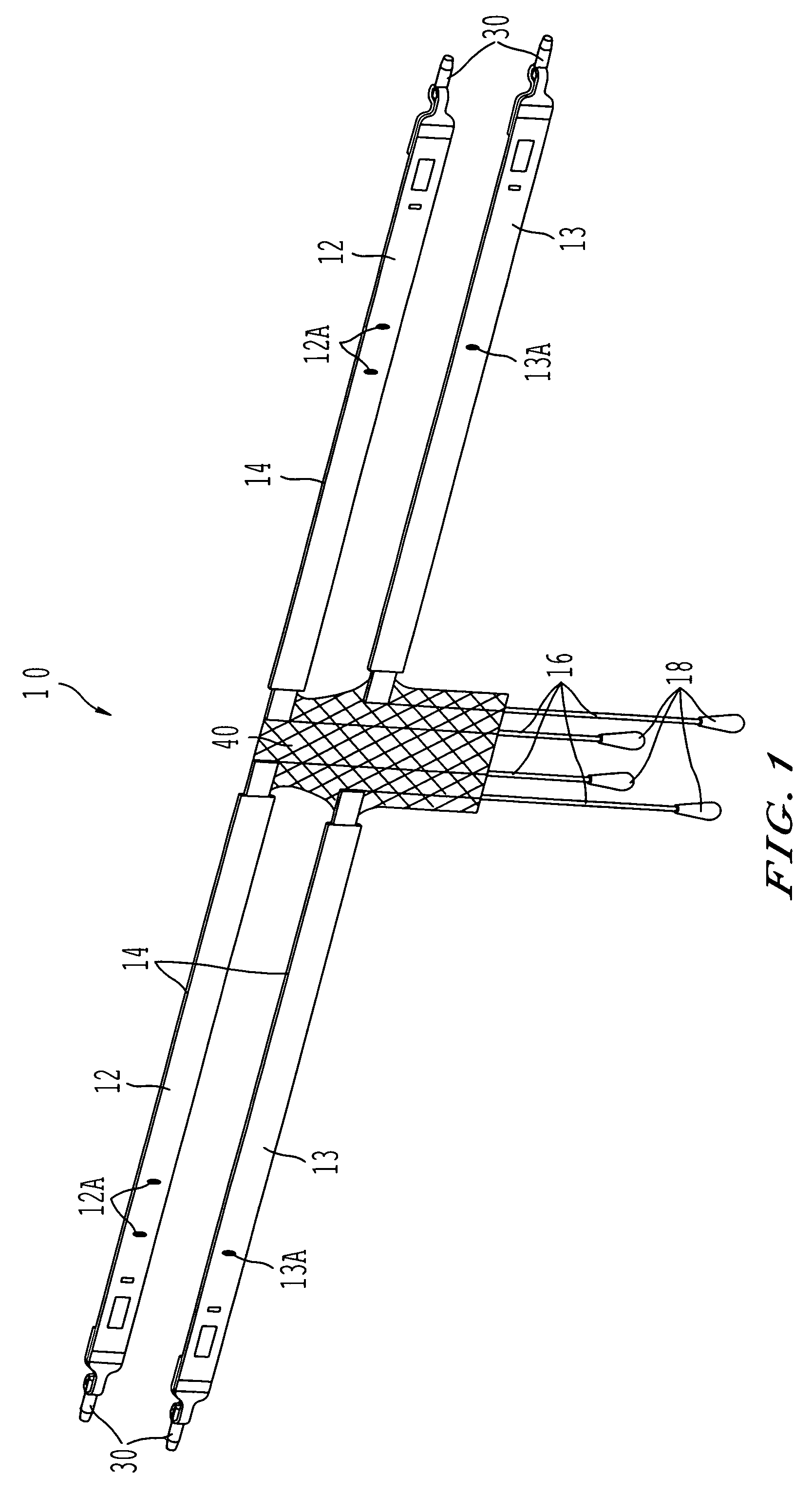
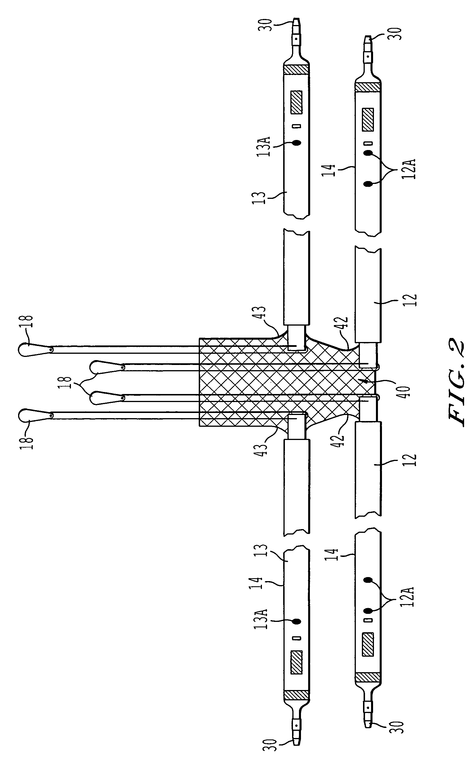
[0059]FIGS. 1 and 2 illustrate a surgical support apparatus 10 of the present invention. The apparatus 10 is configured to be surgically implanted in a female patient to repair anterior prolapse of the vagina. The present invention may be used to correct central defects, midline defects, or both midline and central defects at once. In the embodiment shown in FIGS. 1 and 2, apparatus 10 comprises two superior straps 12, two inferior straps 13, a support member 40, and four loosening sutures 16. Each of straps 12 and 13 include a connector 30. Each strap 12 and 13 is covered by a sheath 14. Each suture 16 includes a tab 18. Straps 12 and 13 are connected to tabs 42 and 43 of support member 40 by known means.

[0060]In one embodiment, sheath 14 is made of polyethylene. Other material may be used, such as polypropylene, nylon, polyester, or Teflon. The sheath is configured to be removed from the strap after the strap is in the correct position in the body.

[0061]In one embodiment, straps 1...

second embodiment

[0069]FIG. 5 illustrates the surgical support apparatus of the present invention. Apparatus 110 includes a biological graft for a support member 140. To attach the graft to straps 12 and 13, clamps 150 are used to hold the surfaces of the strap and member together. The surfaces are then secured together, as discussed below in the method for preparing the biologic graft. Straps 12 and 13, sheaths 14, and connectors 30 are described above.

[0070]In another embodiment, biologic graft comes in a kit already secured to straps 12 and 13. In this case, the preparation method below is unnecessary.

third embodiment

[0071]FIG. 6 shows the surgical support apparatus of the present invention. Apparatus 210 includes straps 12 and 13, sheaths 14, and support member 240. In this embodiment, support member 240 and straps 12 and 13 are continuously knitted. Thus, there is no seam between the straps and support member, as they are one continuous piece. This results in a thinner transition area 243 from the straps to the support member, which results in a less bulky apparatus for installment into the patient. An apparatus that is less bulky will be less likely to abrade the surrounding tissue.

[0072]The support member is knitted with a first bar pattern, and the straps are knitted with a second bar pattern. This allows larger pores in the support member, creating a support member that is more flexible and more likely to allow tissue ingrowth. A second bar pattern for the straps allows a smaller pore size for the straps, creating a strap that can carry a larger load with a smaller, less intrusive strap wi...


PUM


Abstract

A method for cystocele repair comprising the steps of: establishing four pathways in tissue around a bladder of a patient, introducing a strap into each of said pathways, and positioning beneath said bladder of said patient a support member having each said strap connected thereto such that said bladder of said patient is supported by said support member and a bulge of said bladder into a vagina of said patient is reduced.

Description

BACKGROUND OF THE INVENTION[0001]1. Field of the Invention[0002]Urogenital Surgery[0003]2. Description of the Related Art[0004]Female genital prolapse has long plagued women. It is estimated by the U.S. National Center for Health Statistics that 247,000 operations for genital prolapse were performed in 1998. With the increasing age of the U.S. population, these problems will likely assume additional importance.[0005]Vaginal prolapse develops when intra-abdominal pressure pushes the vagina outside the body. In a normal situation, the levator ani muscles close the pelvic floor. This results in little force being applied to the fasciae and ligaments that support the genital organs. Increases in abdominal pressure, failure of the muscles to keep the pelvic floor closed, and damage to the ligaments and fasciae all contribute to the development of prolapse.[0006]Many techniques have been tried to correct or ameliorate the prolapse and its symptoms, with varying degrees of success. Nonsurg...

Claims


Application Information

Patent Timeline
Patent Type & Authority Patents(United States)
IPC IPC(8): A61F2/00A61B17/00A61B17/04A61B17/06
CPCA61B17/06066A61B17/06109A61F2/0045A61B2017/0046A61B2017/00805A61B2017/0496A61B2017/06009A61B2017/06076A61F2002/3071A61F2002/30713A61F2002/30714A61F2250/0085A61F2250/0087A61F2250/0089
Inventor MONTPETIT, KAREN PILNEYANDERSON, KIMBERLY AWATSCHKE, BRIAN P
Owner ASTORA WOMENS HEALTH
Why Eureka
Try Eureka