Pubovaginal sling implanter and procedure for the usage

Inactive Publication Date: 2006-09-28
WAN SHAW P +1
View PDF6 Cites 93 Cited by
  • Summary
  • Abstract
  • Description
  • Claims
  • Application Information

AI Technical Summary

Benefits of technology

[0018] Accordingly, the main purpose of this invention is to provide a smooth passage of the sling material into the body that would minimize the amount of tissue damage and by not having to slide the sling material or to drag a dilator through the tissue cavity. This

Problems solved by technology

Tissue damage results as the plastic sheath is pulled with the needle and the plastic sheath slides through the tissue.
Implantation methods like Sep. 2, 2003, Staskin, Neisz & Westrum & Rocheleau, U.S. Pat. No. 6,612,977 uses a p

Method used


Image

  • Pubovaginal sling implanter and procedure for the usage
  • Pubovaginal sling implanter and procedure for the usage
  • Pubovaginal sling implanter and procedure for the usage

Examples


Embodiment Construction

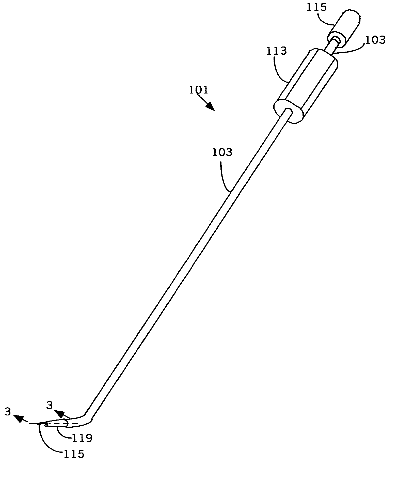
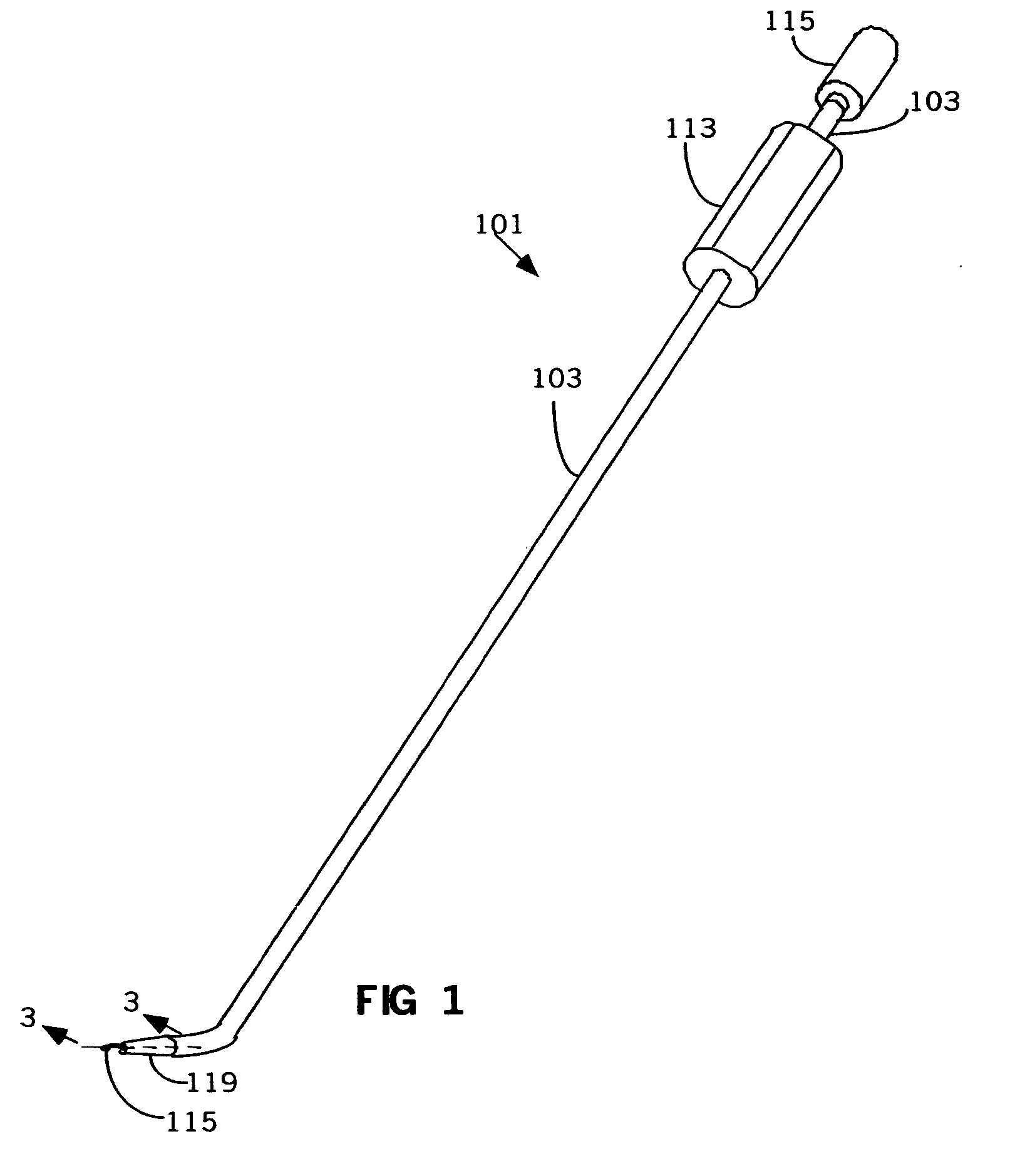
[0046] Referring now to the drawings, and first more particularly to FIGS. 1 and 2, a Pubovaginal Sling Implanter of the present invention is indicated in its entirety by the reference numeral 101. The surgical instrument 101 is used for the implantation of a Pubovaginal Sling for treating female stress urinary incontinence

[0047] As shown in FIG. 1, the instrument 101 comprises a substantially rigid guide tube 103, a handle assembly 113, a flexible shaft assembly 115 and a detachable tapered tube 119.

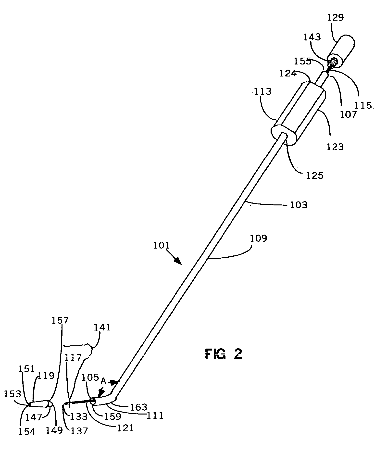
[0048] As shown in FIG. 2 and exploded FIG. 4, the instrument 101 comprises a substantially rigid guide tube 103 having opposite open ends 105 and 107, which are distal and proximal relative to a person using the instrument. The guide tube 103 has a stem portion 109 and a distal portion 111 extending generally laterally with respect to the stem portion 109 at an angle “A” not substantially less than 90 degrees. This angle is preferably 90-170 degrees and more preferably about 165 degr...


PUM


Abstract

A surgical instrument used for the implantation of a Pubovaginal Sling for treating female stress urinary incontinence comprising of a guide tube, a detachable tapered tube and a flexible shaft. These elements penetrates the body cavity, place the standard Pubovaginal Sling in the proper place and helps obtaining the proper tension of the Sling.

Description

BACKGROUND [0001] 1. Field of Invention [0002] This invention relates to a surgical instrument used for the implantation of a Pubovaginal Sling for treating female stress urinary incontinence. [0003] 2. Description of Prior Art [0004] Present techniques have shown the need for improved surgical instrumentation to minimize the risks of hemorrhage, injury to internal organs, sling erosion and postoperative urinary retention. [0005] A literature review has shown the present techniques are associated with 5% of hemorrhagic complications, 4% bowel and bladder injury, 1% of graft erosion, and 3% of urinary retention. [0006] Accordingly we have developed an instrument that would minimize the risks of the above-mentioned complications. [0007] For many years, surgeons have used sling procedures to treat female urinary stress incontinence (SUI) in women. This procedure is referred to as the Pubovaginal Sling procedure. The procedure creates a support to the urethra and bladder neck complex. P...

Claims


Application Information

Patent Timeline
IPC IPC(8): A61F2/00
CPCA61B17/0482A61B17/0483A61B2017/00805A61B2017/06042A61F2/0045
Inventor WAN, SHAW P.MARTINEZ, ROSENDO
Owner WAN SHAW P
Why Eureka
Try Eureka