Outlet box knockout

a technology for outlet boxes and knockouts, which is applied in the direction of caps, liquid handling, transportation and packaging, etc., can solve the problems of difficult arrangement and difficulty in molding the knockouts in a manner, and achieve the effect of minimizing the possibility of other knockouts and easy knockout removal

Inactive Publication Date: 2008-04-08
THOMAS & BETTS INT INC
View PDF38 Cites 33 Cited by
  • Summary
  • Abstract
  • Description
  • Claims
  • Application Information

AI Technical Summary

Benefits of technology

[0005]Weakened areas are provided in the box wall at the bottom of the inner and intermediate grooves so that removal of the inner knockout will not result in removal of the intermediate or outer knockouts, and so that removal of both the inner and intermediate knockouts will not result in removal of the outer knockout.
[0008]It is another object of the invention to provide a knockout arrangement that provides easy knockout removal while minimizing the possibility that other knockouts will be undesirably displaced.

Problems solved by technology

It is difficult to mold the knockouts in a manner that provides easy removal of a desired knockout without dislodging other knockouts.
It also is difficult to provide an arrangement for molding the knockouts into the box walls while ensuring plastic flow to the knockout areas during the molding process.

Method used


Image

  • Outlet box knockout
  • Outlet box knockout
  • Outlet box knockout

Examples


Embodiment Construction

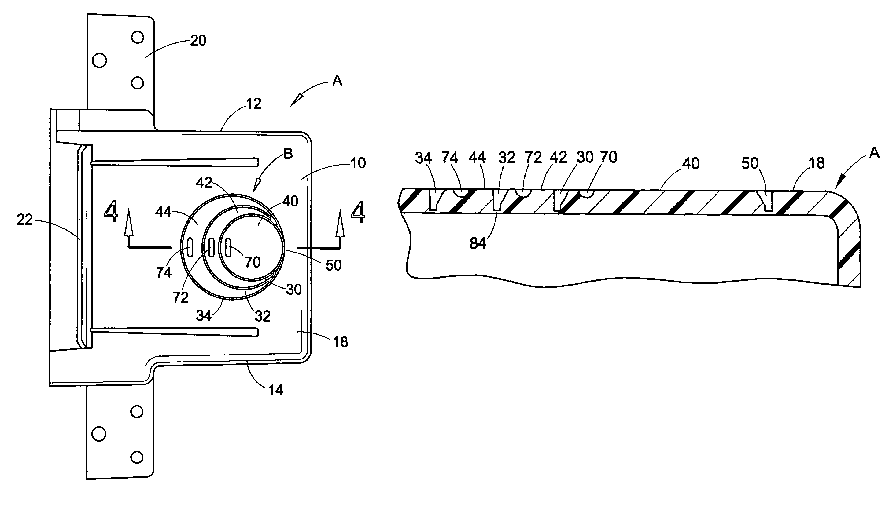
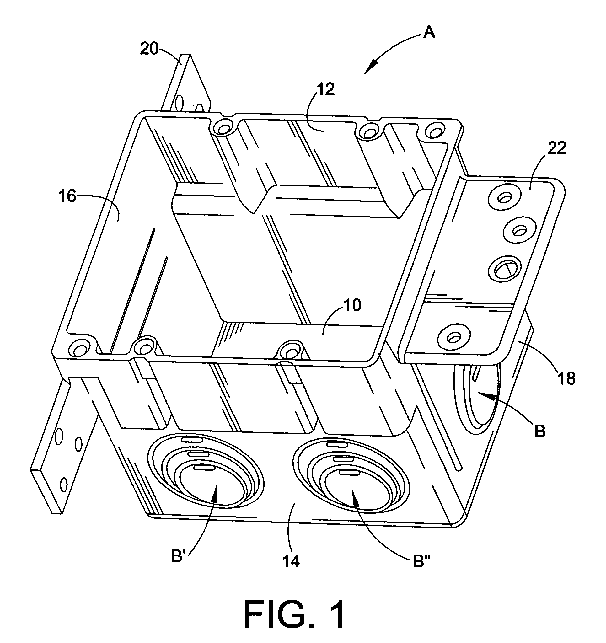
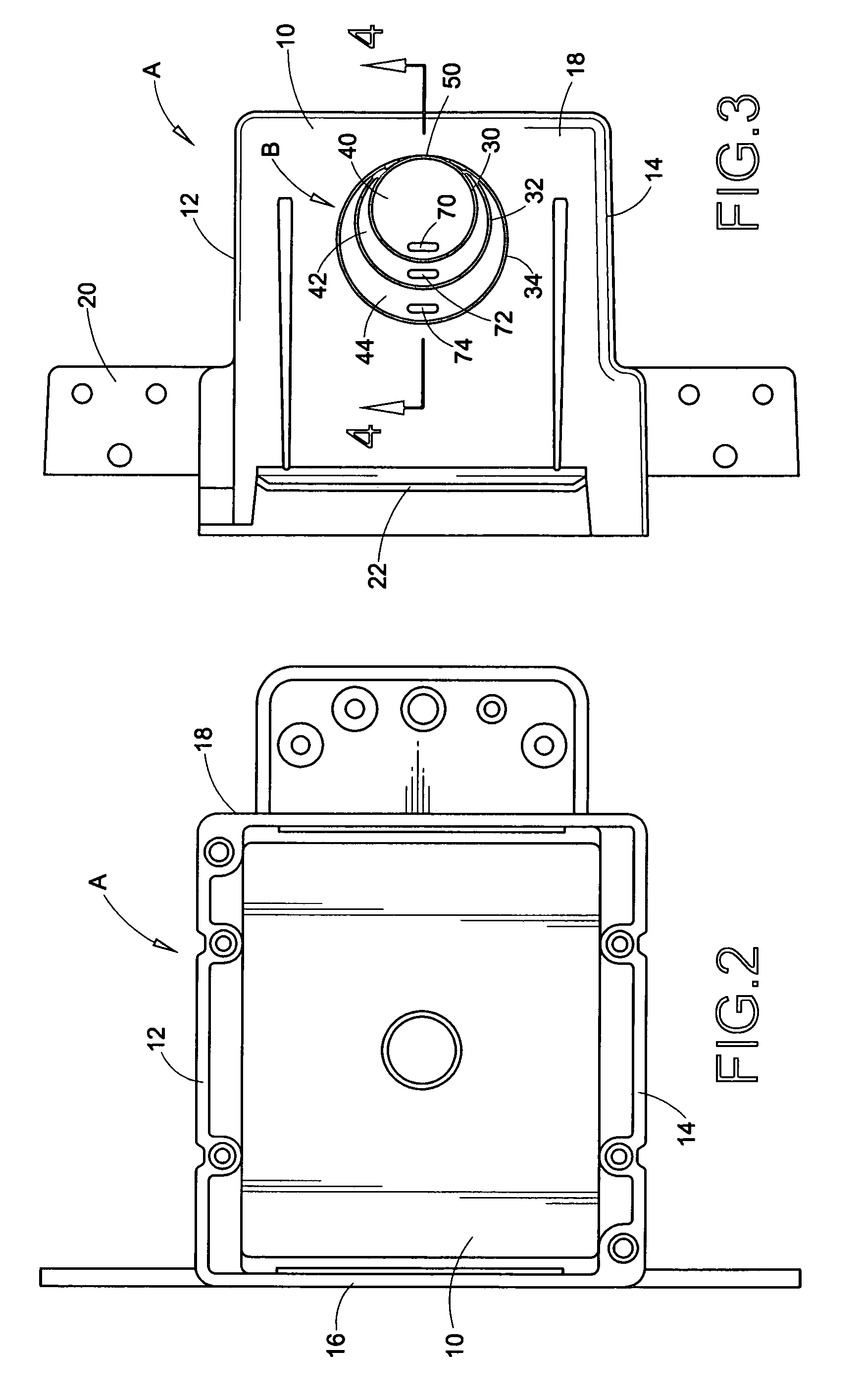
[0015]Referring now to the drawing, wherein the showings are for purposes of illustrating a preferred embodiment of the invention only and not for purposes of limiting same, FIG. 1 shows an electrical outlet box molded of plastic material such as, but not necessarily limited to, PVC or polycarbonate. Box A has a bottom wall 10, opposite side walls 12, 14 and opposite end walls 16, 18. Box A has an open front end opposite from bottom wall 10. Although a two gang box is illustrated in the drawings, it will be appreciated that the invention can be used with single gang boxes as well as with boxes, enclosures and housings of many other types. Box A has mounting flanges 20, 22 for attaching same to wall studs or to joists.

[0016]FIG. 3 shows a knockout arrangement B that is molded into wall 18. It will be recognized that the knockout arrangement of the present application may be provided in one or more of the box walls and that some box walls may have more than one knockout arrangement. F...


PUM


Abstract

An electrical outlet box molded of plastic material has a knockout arrangement in a box wall that is formed by inner, intermediate and outer circular grooves that are eccentrically positioned to overlap at a tangent location and define inner, intermediate and outer eccentrically positioned circular knockouts. The grooves vary in depth from a minimum depth at the tangent location to a maximum depth opposite from the tangent location. Areas of increased weakness are provided in the box wall at the bottoms of at least the inner and intermediate grooves, and screwdriver slots are provided in the knockouts opposite from the tangent location.

Description

BACKGROUND OF THE INVENTION[0001]This application relates to electrical outlet boxes that are molded of plastic material and have knockouts molded into the box walls. However, it will be appreciated that the invention has broader aspects, and that the knockout arrangement of the present application can be used in other types of housings and enclosures.[0002]It is common to mold knockouts in the walls of electrical boxes to provide openings for attaching conduits and fittings to the box. It is difficult to mold the knockouts in a manner that provides easy removal of a desired knockout without dislodging other knockouts. It also is difficult to provide an arrangement for molding the knockouts into the box walls while ensuring plastic flow to the knockout areas during the molding process.SUMMARY OF THE INVENTION[0003]A knockout arrangement in a plastic wall includes inner, intermediate and outer circular grooves that are eccentric relative to one another and overlap at a tangent locati...

Claims


Application Information

Patent Timeline
Patent Type & Authority Patents(United States)
IPC IPC(8): H02G3/08H02G3/18B65D6/40
CPCH02G3/085
Inventor HULL, ERIC G.TURCOVSKY, GREGORY D.REVLOCK, SR., DENNIS P.
Owner THOMAS & BETTS INT INC
Why Eureka
Try Eureka