

Erosion control barrier
- Summary
- Abstract
- Description
- Claims
- Application Information
AI Technical Summary
Benefits of technology
Problems solved by technology
Method used
Image


Examples
Embodiment Construction
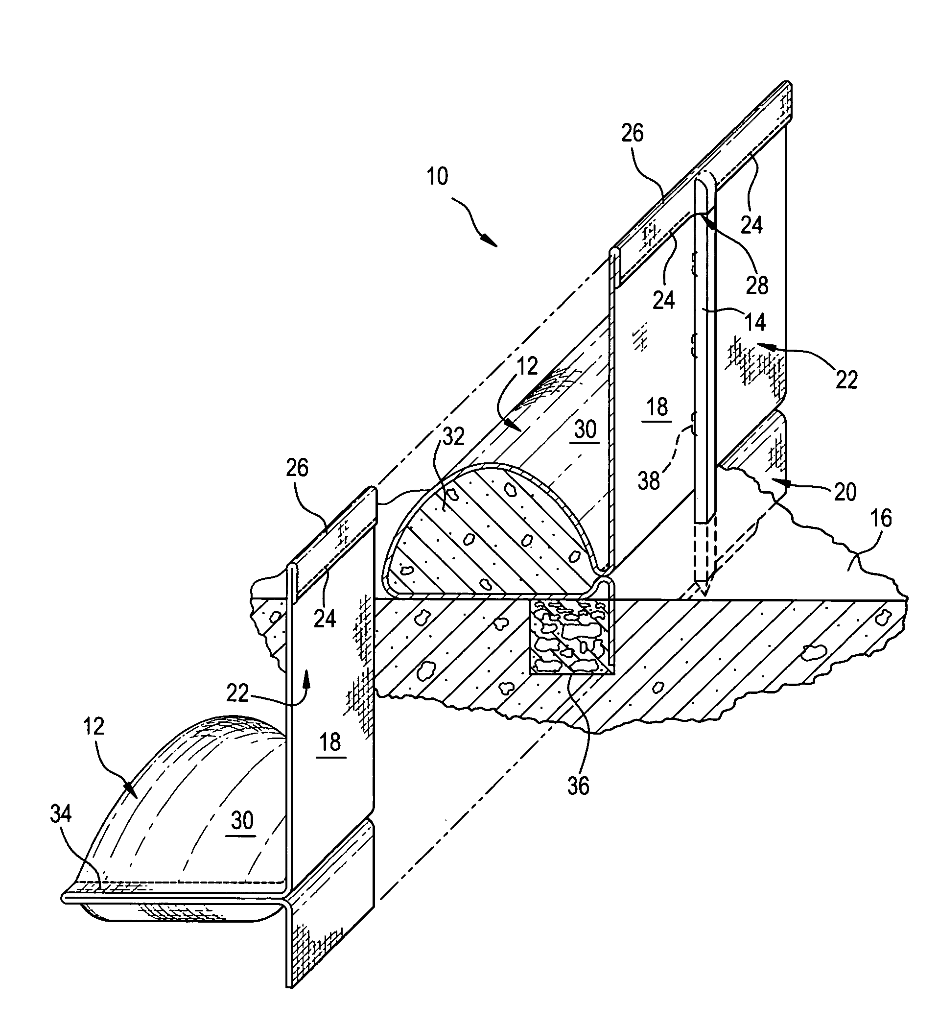
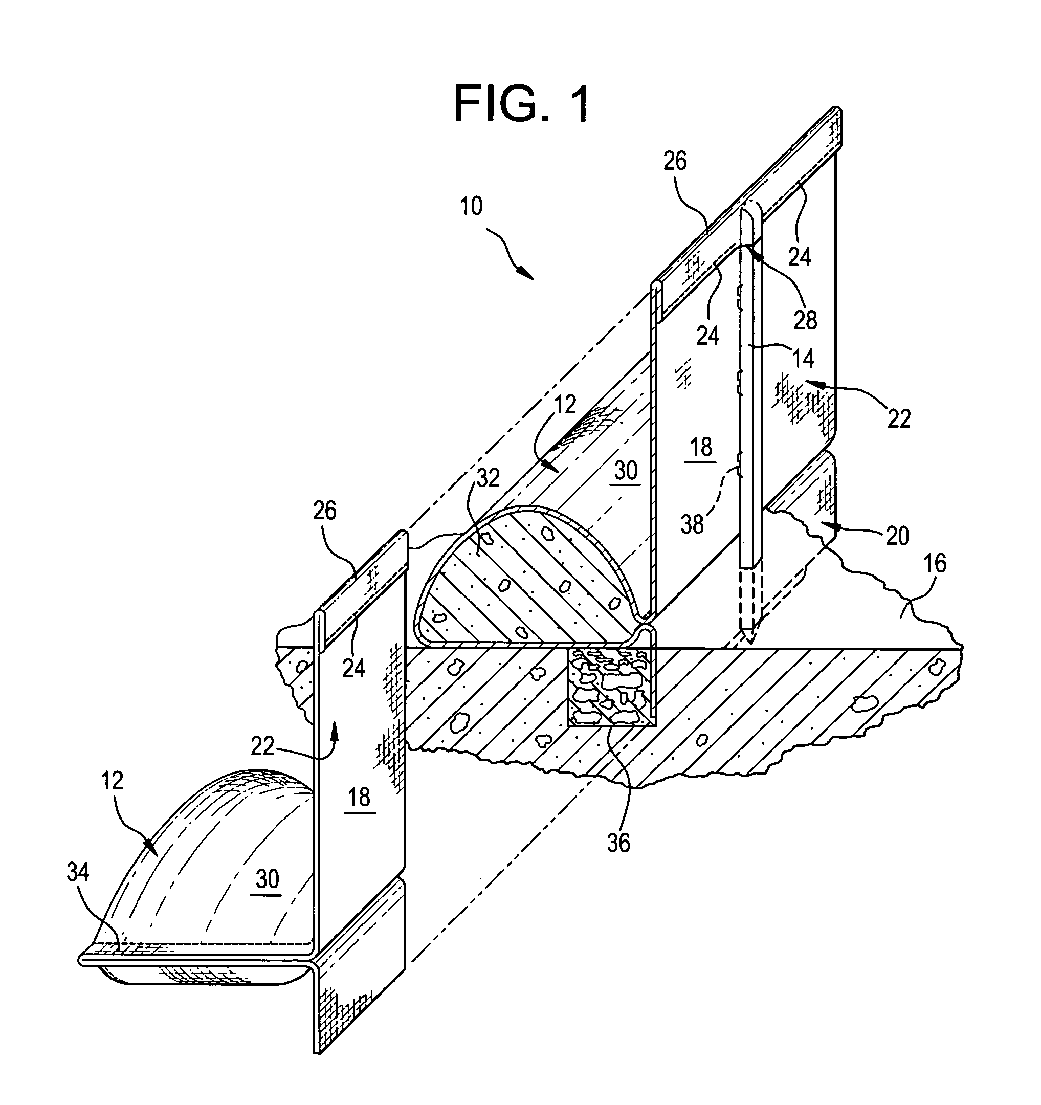
[0020]Referring now to FIG. 1, an erosion control barrier in accordance with the present invention is shown at 10. Barrier 10 includes an elongated boom 12 anchored by posts as at 14 driven into the ground 16. Extending upwardly from boom 12 is an aboveground wing 18 that traps runoff that may spill over boom 12. Extending downwardly from boom 12, however, is an underground wing 20 that prevents runoff from passing beneath boom 12.
[0021]The principal features of barrier 10 are made by folding and stitching a rectangular sheet of cloth 22. As shown, the top of cloth sheet 22 is folded upon itself and stitched along the length of the overlapping parts by a plurality of laterally spaced seams 24 so as to produce a hem 26 whose interior is accessed through pockets or openings 28 provided by gaps between seams 24. Sheet 22 is also folded a second time and stitched to produce a tube 30 spaced from, and parallel to, hem 26 and a pair of wings 18 and 20 extending outwardly from tube 30. Tub...
PUM
 Abstract
Description
Claims
Application Information