Device for lifting and stabilizing loads

a technology for lifting and stabilizing loads, applied in the direction of lifting equipment, load-engaging elements, transportation and packaging, etc., can solve the problems of not being completely implemented, achieve the effect of simple technical means, stable and rigid crossmember guidance, and achieve the stability of the crossmember in and against the direction of travel

Active Publication Date: 2008-04-15
SIEMENS AG
View PDF7 Cites 20 Cited by
  • Summary
  • Abstract
  • Description
  • Claims
  • Application Information

AI Technical Summary

Benefits of technology

[0007]An object of the present invention, is to improve a device for lifting and stabilizing loads of the generic type so that, with a simple and lightweight construction, a stable and swing-free transportation of loads is also possible in and against the direction of travel.
[0011]The present invention has in practice turned through 90° the pivot axes of the deflection pulleys as provided in the prior art, so that the axes in the invention run at right angles to the pivot axes of the telescopic struts. The double 90° deflections on the link-side end of the telescopic struts has the effect of routing the stay section between the 90° deflections essentially through the center point of the pivot movement, i.e. the support of the telescopic struts. This causes the stay to twist when passing through the support of the telescopic struts during a pivoting or lifting movement of the telescopic struts, but not to change its length. This means that the synchronized stay does not require the indispensable elasticity of the known solution, so that a very rigid suspension stabilization is achieved.
[0015]The present invention differs markedly from the stay routing proposed in the German Patent Application DE 36 36 459 A1 and avoids the disadvantages arising there in favor of an especially rigid and stable crossmember guidance. The fact that the stays are routed in the invention in the deflection area in the pivot point of the telescopic struts and through the support bolts of the telescopic struts means that, when the crossmember is raised or lowered with the load, the stay length remains practically constant, so that the stability of the crossmember in and against the direction of travel can be achieved with simple technical means.

Problems solved by technology

This can however not be completely implemented since in each deflection area two stays are routed alternately to the two telescopic struts but care must be taken that these stays are routed lying as closely as possible to each other in parallel to the pivot axis of the telescopic struts.

Method used


Image

  • Device for lifting and stabilizing loads
  • Device for lifting and stabilizing loads
  • Device for lifting and stabilizing loads

Examples


Embodiment Construction

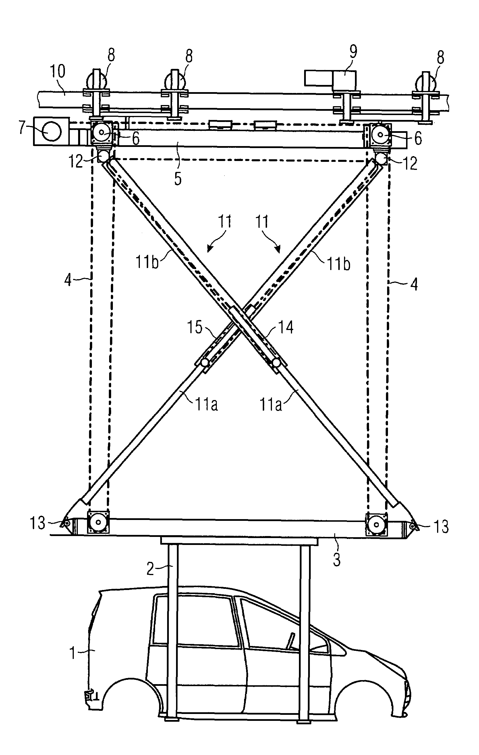
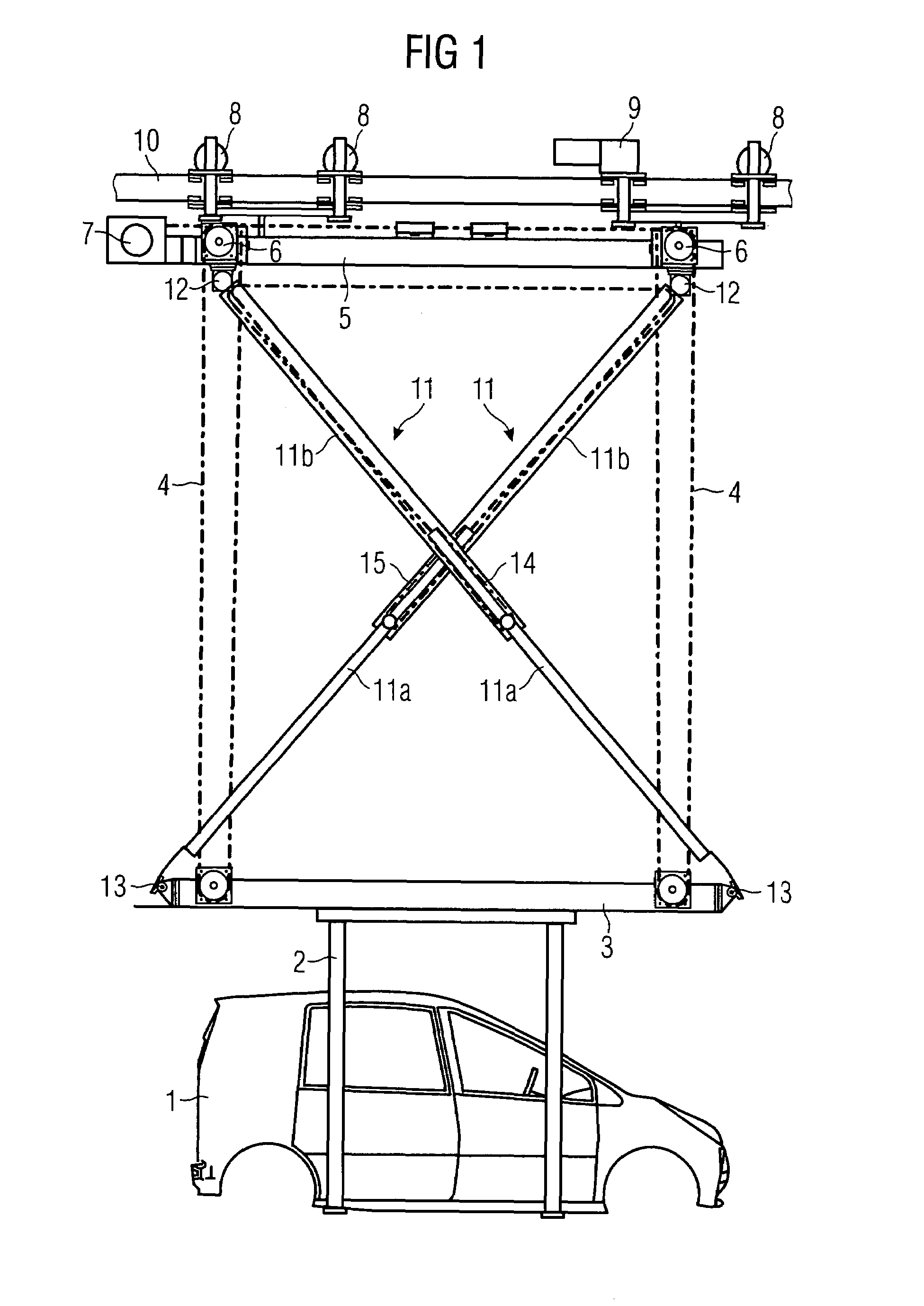
[0021]FIG. 1 shows a simplified schematic diagram of the inventive device for lifting and stabilizing loads. A motor vehicle body 1 is suspended from the crossmember 3 by a suspension unit, which for its part is suspended to allow it to be raised or lowered via the lifting stays 4 on the frame 5, with the lifting stays 4 being routed via deflection pulleys 6 to central lifting gear 7 through which the raising and lowering of the crossmember can be initiated. The frame 5 is driven on the wheels 8 and by a motor drive unit 9 along the horizontal rail 10 in order to transport the motor vehicle body 1 from one assembly point to the next.

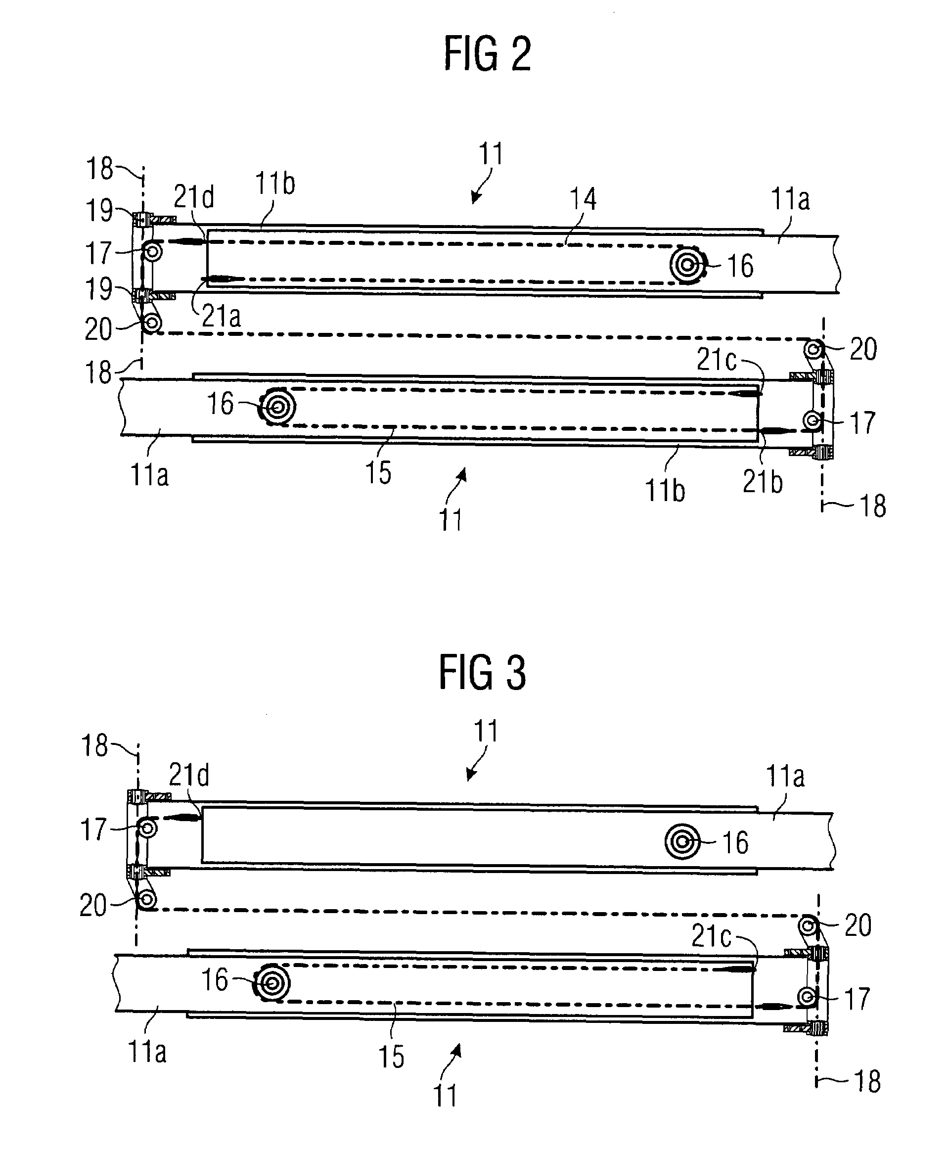
[0022]When the lifting stay 4 is wound back onto the drums of the lifting gear 7 the telescopic struts 11 provided for the stabilisation of the crossmember in the direction of travel, which are arranged to intersect between the frame 5 and the crossmember 3, change their length and make it possible to move the crossmember 3 closer to the frame 5 and ther...


PUM


Abstract

It is described a device for lifting and stabilizing loads, comprising a frame and a height-adjustable crossmember, which is located below said frame, bears the load, and is stabilized by two intersecting telescopic struts that are hinged on the crossmember so that they can pivot, said struts being in turn secured against modifications in length by means of two stays. Each stay, which is deflected by a deflection pulley provided on the frame or crossmember in the vicinity of the hinged ends of the telescopic struts, is guided in a parallel manner to or in an essentially coaxial manner with the pivoting axis of the telescopic strut to an additional (third) deflection pulley and is then conducted to the other respective telescopic strut.

Description

CROSS REFERENCE TO RELATED APPLICATIONS[0001]This application is the U.S. National Stage of International Application No. PCT / EP2005 / 054192, filed Aug. 25, 2005 and claims the benefit thereof. The International Application claims the benefits of German application No. 10 2004 045 516.3 DE filed Sep. 20, 2004, both of the applications are incorporated by reference herein in their entirety.FIELD OF INVENTION[0002]The invention relates to a device for lifting and stabilizing loads, especially suspension units for motor vehicles or motor vehicle parts.BACKGROUND OF INVENTION[0003]Such devices are primarily used in automobile production to transport motor vehicle parts or the motor vehicle to be produced in its respective stage of production between the individual assembly points. To this end a frame is usually able to be moved horizontally on a rail, the height of a crossmember can be adjusted via the stay hinged onto it using lifting gear arranged on the frame, with the conducting of t...

Claims


Application Information

Patent Timeline
Patent Type & Authority Patents(United States)
IPC IPC(8): B66D1/36
CPCB66C13/06
Inventor ASSMANN, ROLAND HEINZ
Owner SIEMENS AG
Why Eureka
Try Eureka