Spinal traction device and method

a spinal traction and traction device technology, applied in the field of medical spinal traction devices, can solve the problems of many prior art devices being bulky, difficult to install and/or use, and often suffering from a number of drawbacks

Inactive Publication Date: 2008-04-15
MEYERS RYAN
View PDF7 Cites 21 Cited by
  • Summary
  • Abstract
  • Description
  • Claims
  • Application Information

AI Technical Summary

Benefits of technology

[0007]A bending coupling couples the body sled to the fixed base such that the individual's upper torso can be bent to the left or right with respect to the individual's lower torso. A flexion and extension coupling couples the body sled to the fixed base such that the individual's upper torso can be slanted upward or downward with respect to the individual's lower torso. In an alternative embodiment, the body sled has a first portion and a second portion that are independently movable with respect to one another such that a user can produce cervical traction in their neck region.

Problems solved by technology

Unfortunately, these devices typically suffer from a number of drawbacks.
For instance, many prior art devices are often bulky, heavy and difficult to install and / or use.
In addition, the prior art devices are often very expensive and complex.
As a result, they are typically not very portable and, thus, are more suitable for use in a hospital or clinical setting than they are for use in a home.
Moreover, the lumbar and cervical traction devices that are intended for home use tend to be very limited in function and versatility.
Prior art lumbar traction devices also tend to be uncomfortable and difficult to operate properly.
In particular, lumbar traction units use belts or girdles that restrict breathing and have difficulty securing joints that are not being treated.
Prior art lumbar and cervical traction devices which apply traction when the user is in the prone position are limited, if not rare.

Method used


Image

  • Spinal traction device and method
  • Spinal traction device and method
  • Spinal traction device and method

Examples


Embodiment Construction

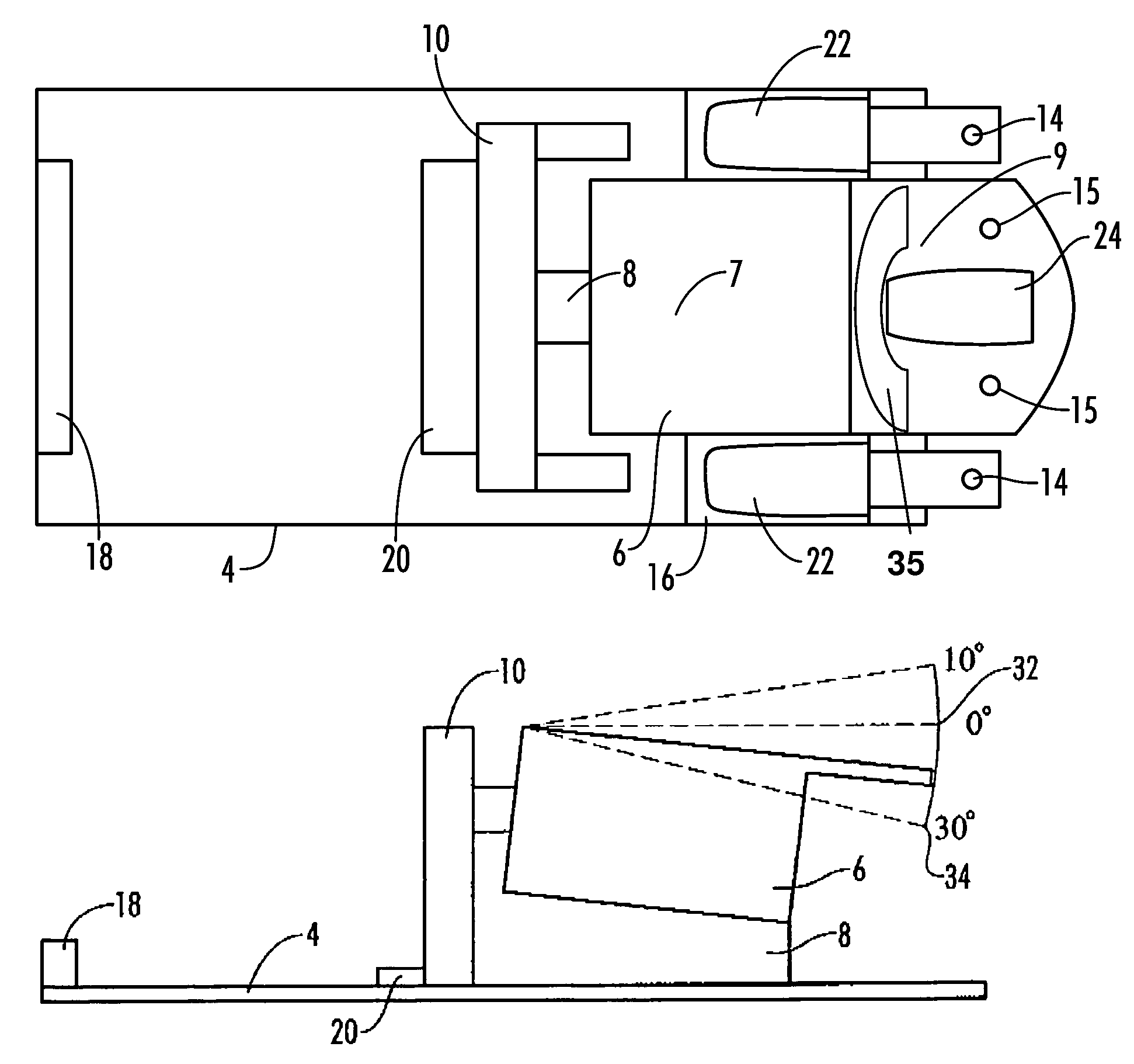
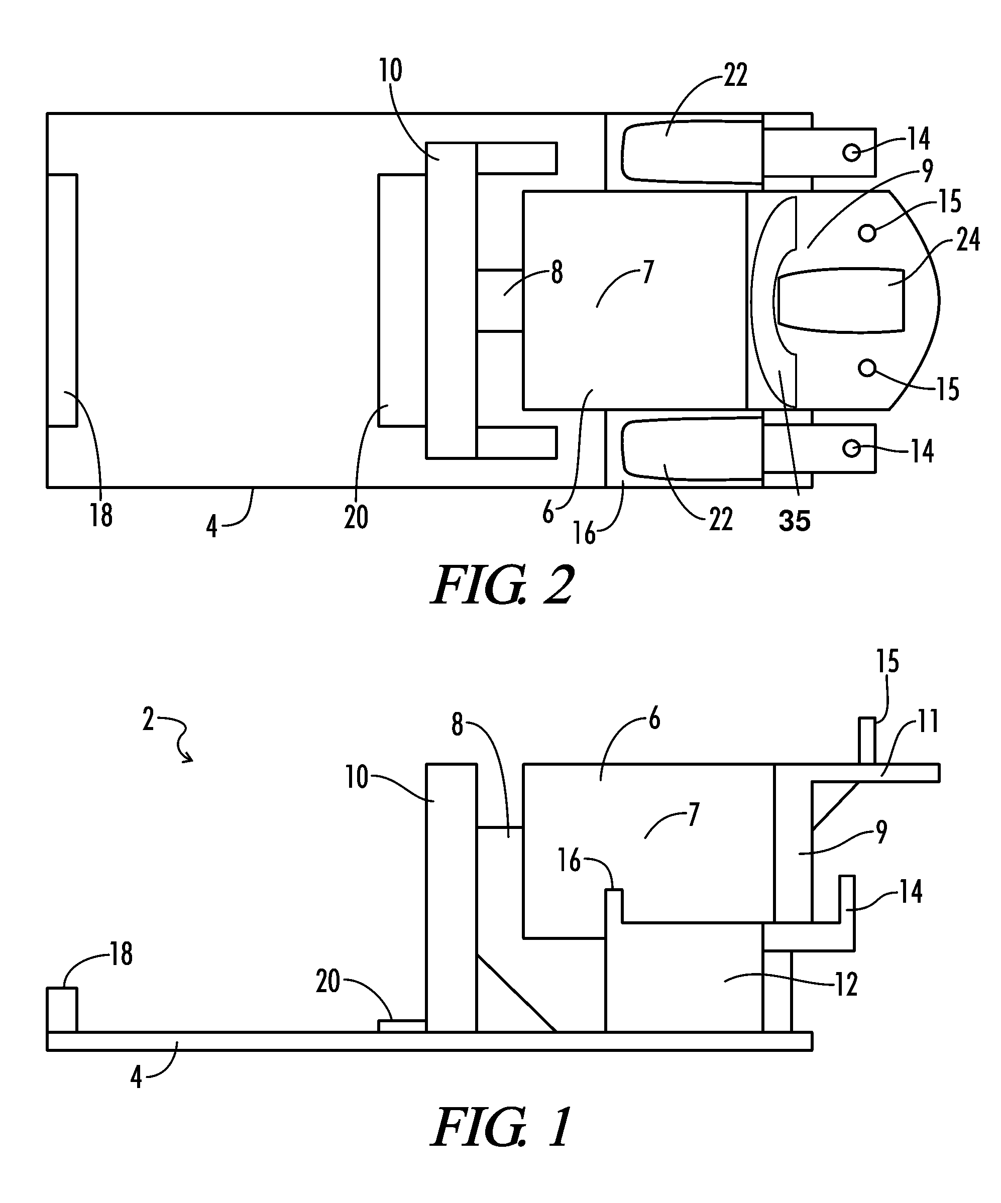
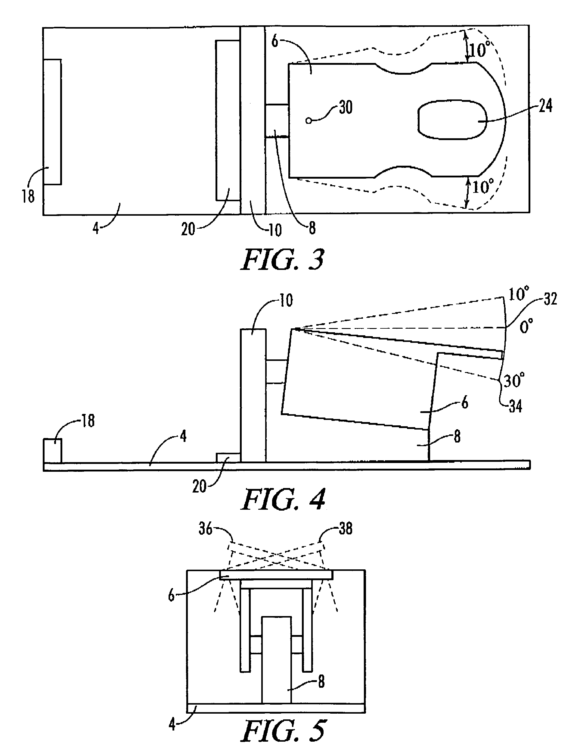
[0015]Referring now to FIGS. 1 and 2, a preferred embodiment of the present lumbar traction device 2, for treating back problems associated with compression of the spine is shown. The lumbar traction device 2 is mounted on a substantially flat base 4 that is designed to rest on a substantially flat surface such as a floor. A moveable body sled 6 for supporting the upper torso of a user is slideably coupled to a sled support 8 with extension glides, tracks, or bars that allow for forward and backward horizontal motion. Alternatively, rockers or gliders can be used to provide forward and backward movement to the body sled 6 in a manner similar to that used in conjunction with a rocking chair.

[0016]The sled support 8 is firmly secured to the flat base 4. A cushioned head support 11 having a facial opening 24 for receiving the face of a user lying face down on the body sled 6 extends from the body sled 6. A thigh rest 10 for restraining the lower torso of a user is positioned in close p...


PUM


Abstract

A spinal traction / decompression device suitable for home or clinical treatment of lumbar and cervical spine pathology. The traction apparatus has a substantially flat upper body support that is moveable with respect to a fixed base. The upper body support is adapted to receive the upper torso of an individual leaning forward in a prone position while kneeling on a knee cushion. A pelvis / hip restraining portion holds the individual's lower torso in position with respect to the fixed base when the upper body support is moved. Lumbar traction may be induced by a user positioning their upper torso on the upper body support and moving it forward or backward with respect to the fixed base. The upper body support may also be divided into two independently moveable sections such that cervical traction can be induced in a neck region of a user. The traction force is preferably supplied by the individual pushing or pulling the upper body support forward with their arms. The upper body support may rotate, side bend, flex or extend with respect to the fixed base to alter the position of the spine when the lumbar traction is induced.

Description

CROSS-REFERENCES TO RELATED APPLICATIONS[0001]Not ApplicableSTATEMENT REGARDING FEDERALLY SPONSORED RESEARCH OR DEVELOPMENT[0002]Not ApplicableREFERENCE TO SEQUENCE LISTING OR COMPUTER PROGRAM LISTING APPENDIX[0003]Not ApplicableBACKGROUND OF THE INVENTION[0004]The present invention relates generally to the field of medical spinal traction devices. It is well known in the prior art that a variety of spinal disorders can be treated by applying tension to the spine. The application of tension or traction to the spine serves to displace forces and relieve pressure of the spine and, thereby, facilitate the treatment a variety of conditions. Accordingly, a number of prior art lumbar and cervical traction devices have been developed for applying traction to the human spine. Unfortunately, these devices typically suffer from a number of drawbacks. For instance, many prior art devices are often bulky, heavy and difficult to install and / or use. In addition, the prior art devices are often ve...

Claims


Application Information

Patent Timeline
Patent Type & Authority Patents(United States)
IPC IPC(8): A61F5/00A61G15/00A61H1/00
CPCA61H1/0292A61H2203/0412A61H2203/045
Inventor MEYERS, RYAN
Owner MEYERS RYAN
Why Eureka
Try Eureka