
Device and method for culturing cells

a cell culture and cell technology, applied in the field of cell culture technology, can solve the problems of flow-rate and pressure change, difficulty in using a one-way liquid supply means such as a micro syringe, etc., and achieve the effect of eliminating dead space, and preventing the release of cell layers

Active Publication Date: 2008-04-15
FUJIFILM HLDG CORP +1
View PDF9 Cites 13 Cited by
  • Summary
  • Abstract
  • Description
  • Claims
  • Application Information

AI Technical Summary

Benefits of technology

[0007]It is an object of the present invention to construct a culture device optimized for culturing animal cells. Thus, it is an object of the present invention to provide a cell culture device capable of culturing animal cells by supplying different types of flowing media to both surfaces of a culture, capable of simulating blood shearing and substance supply in a medium in contact with the animal cells, and capable of culturing the animal cells while preventing release of cell layers under a condition which is similar with that in a living body. More specifically, it is an object of the present invention to provide a device and method for culturing cells, capable of (1) supplying a substance uniformly to the cells to be cultured; (2) establishing a uniform flow for supplying a substance; (3) eliminating a dead space; and (4) preventing release of cell layers by the flow. Still more specifically, it is an object of the present invention to provide a cell culture device equipped with a control mechanism for establishing a uniform inner pressure in the system.
[0008]In the culturing of cells, a liquid must be supplied for quite a long time and thus it is difficult to use a one-way liquid supply means such as a micro syringe. Instead, a plurality of microsyringes which are alternately operated, a microgear pump, or multiple-head microplunger pump are used. However, these methods have problems that flow-rate and pressure may change at the time of switching. Thus, it is an object of the present invention to provide a device for culturing cells which eliminates these problems. Thus, it is an object of the present invention to reduce pulsation generated in a steady operation when a relatively compact and convenient pump-system is employed in the device, and to reduce variation in the flow-rate taking place when an alternately drived pump such as a multi-head plunger pump is used while switching heads alternately.
[0014]another pocket structure immediately upstream of an outlet pipe in order to suppress the effect of the flow toward the outlet.
[0042]Preferably, a second pressure equalizing mechanism for stabilizing the flow discharged from the culture device is further provided downstream of the downstream flow channel of the cell culture section.

Problems solved by technology

In the culturing of cells, a liquid must be supplied for quite a long time and thus it is difficult to use a one-way liquid supply means such as a micro syringe.
However, these methods have problems that flow-rate and pressure may change at the time of switching.

Method used


Image

  • Device and method for culturing cells
  • Device and method for culturing cells
  • Device and method for culturing cells

Examples


example a-1

(1) Manufacture of Reactor

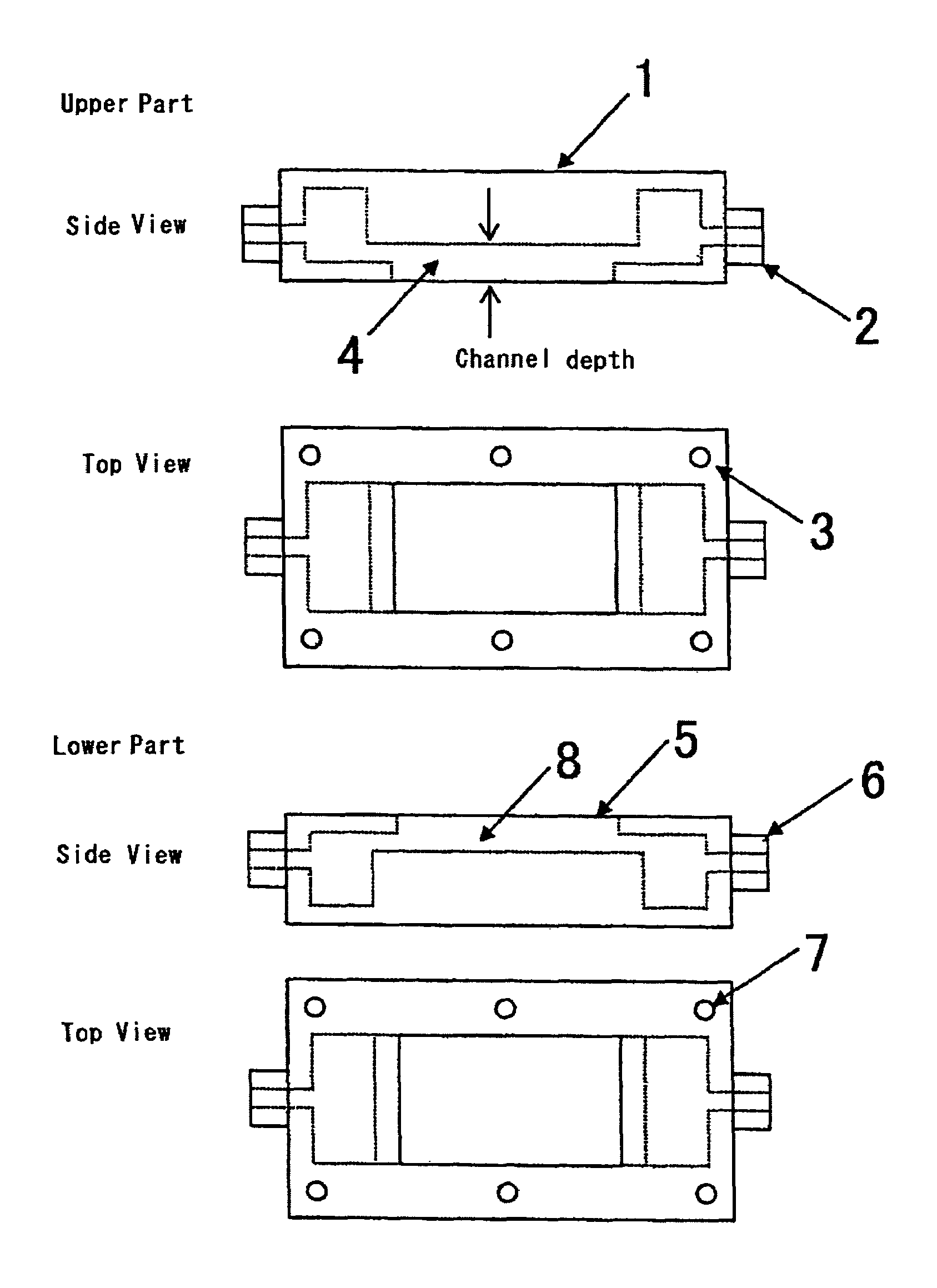
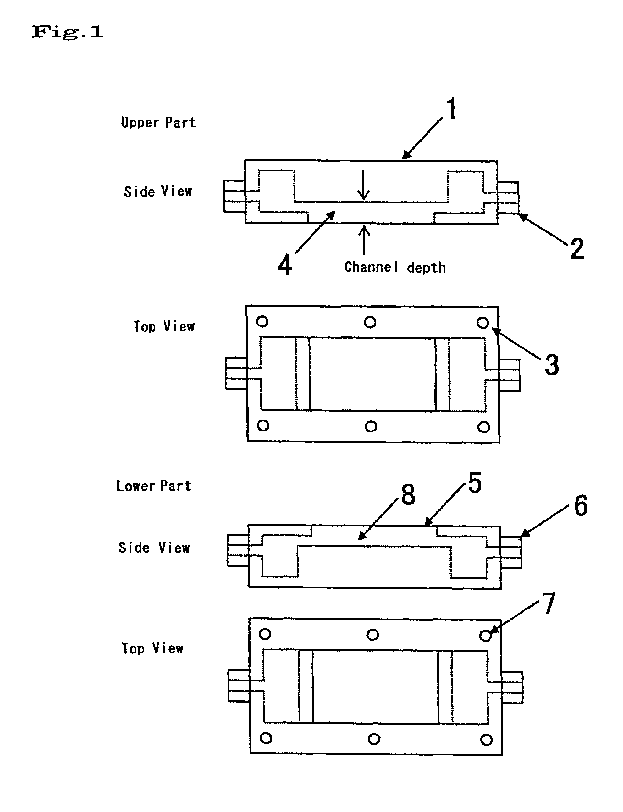
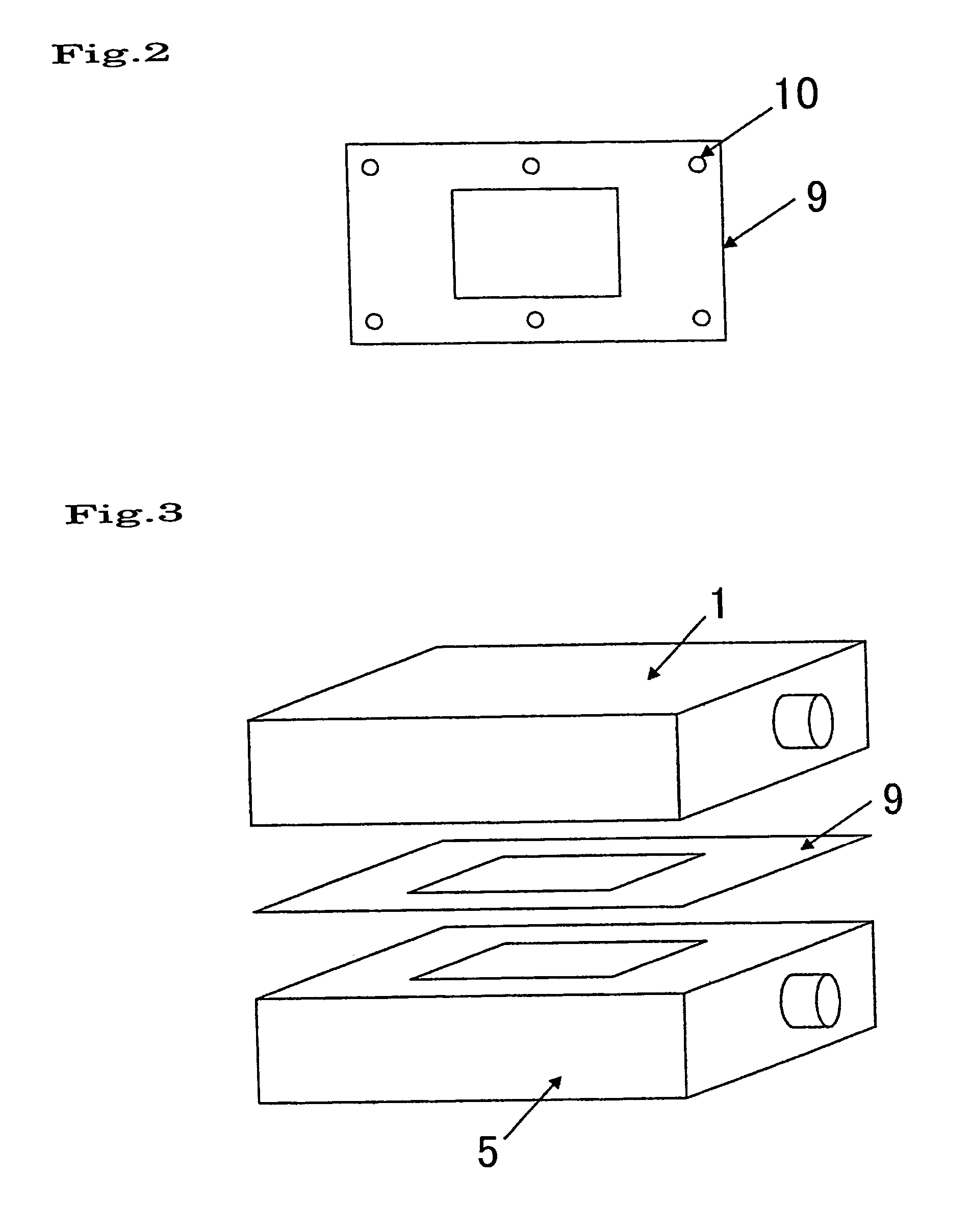
[0127]A bioreactor shown in FIG. 1 was manufactured by processing polymethyl methacrylate board by a mechanical micro-cut processing and polishing the cut surface. The depth of the flow channel formed in the upper part was set at 500 μm, whereas that formed in the lower part was set at 2 mm. Stainless steel of 100 μm thickness was processed as shown in FIG. 2 to prepare a part for holding a water-containing polymer gel film. This stainless steel part was installed in the bioreactor of FIG. 1 to obtain a construct shown in FIG. 3. Note that the figures are schematically drawn, so that dimensions and dimensional proportions are not consistent with those of the actual bioreactor.

(2) Manufacture of Water-containing Polymer Gel Film

[0128]First, 20 g of chitosan (CT-100, manufactured by Wako Pure Chemical Industries, Ltd.) was gradually added to 1000 g of an aqueous acetic acid solution (1% by mass). The solution mixture was stirred at 40° C. for 3 hours to disso...

example a-2

[0141]The cell culture of (3) of Example A-1 was experimented in the same reactor as in (3) of Example A-1 except that the space between the inner wall of the reactor and the water-containing polymer gel film (the depth of the channel of the upper part) was set at 3 mm. As a result, a good culture was obtained. Two problems: leakage at the connecting portion of a hose for supplying a liquid and 5% removal of the cell layer, occurred; however, 90% of the removed cells were alive.

example b-1

Cell Culture Using a Cell Culture Device Having a Pressure Equalizing Mechanism (Pocket Structure)

(1) Manufacture of Reactor

[0142]A reactor was composed of a PMMA resin member with a length of 9 cm and a width of 3 cm, in which a flow channel and a cell culture section were formed, and a member used as a cover placed on the PMMA resin member. An inlet pipe and outlet pipe both having an inner diameter of 1 mm, were arranged at the side of the flow channel. Ahead of the tip of the inlet pipe, a semicircular pocket portion having a radius of 5 mm was provided in a width of 2 cm. A culture solution flow channel with a width of 2 cm and a depth of 500 μm starting from the pocket was formed. Somewhere within the flow channel, a section for placing cells with a width of 2 cm, a length of 2 cm and a depth of 1 mm was provided. Downstream of the section, a flow channel with a width of 2 cm and a depth of 500 μm was provided. Furthermore, a pocket and an outlet pipe were provided downstream ...


PUM

PropertyMeasurementUnit
thicknessaaaaaaaaaa
heightaaaaaaaaaa
thicknessaaaaaaaaaa

Abstract

An object of the present invention is to construct a culture device optimized for culturing animal cells. The present invention provides a device for culturing cells which comprises at least one water-containing polymer gel film for adhering animal cells onto at least one surface of the film, and has a structure capable of supplying different liquids to both sides of the film.

Description

FIELD OF THE INVENTION[0001]The present invention relates to a cell culture technology. More specifically, the present invention relates to a device for culturing cells, a method of culturing animal cells using the device, and cultured animal cells obtained by the method.BACKGROUND ART[0002]In research and development of medicaments, experimental animals have been used for a long time. On the other hand, it is sometimes difficult to find the efficacy and side effects of medicaments on the basis of data of experimental animals due to intrinsic metabolic functions specific to humans. Also, reduction of experimental animals is recently suggested from the viewpoint of an animal protection. In addition, high cost is incurred for clinical trials in humans. For these reasons, it is desired to reproduce artificial organs, in vitro, having the same function as living organs. Recently, regeneration medical techniques have been evolved, and thus construction of such a model has become possible...

Claims


Application Information

Patent Timeline
Patent Type & Authority Patents(United States)
IPC IPC(8): C12M1/00C12M1/12C12M1/36C12N5/00C12M1/38C12N5/02C12M3/00C12M3/04
CPCC12M25/02C12M29/14C12M41/00C12M41/12C12M41/40C12N2533/72
Inventor TSUZUKI, HIROHIKOTODA, SATORUICHIKAWA, YASUNORIKURAHASHI, TETSUOSHIRAISHI, FUMIKO
Owner FUJIFILM HLDG CORP
Learn More