Measuring transducer of vibration-type

a technology of measuring transducer and type, which is applied in the direction of mass flow measurement device, measurement device, instrument, etc., can solve the problems of high material cost and usually also higher processing cost, complicated manufacturing, and the inability to measure the accuracy of the respective inline measuring device to fluctuate significantly, so as to improve the density dependence of the zero point

Active Publication Date: 2008-04-22
ENDRESS HAUSER FLOWTEC AG
View PDF43 Cites 116 Cited by
  • Summary
  • Abstract
  • Description
  • Claims
  • Application Information

AI Technical Summary

Benefits of technology

[0012]An object of the invention, therefore, is to improve the density dependence of the zero point and, as a result, the zero point stability of measuring transducers of the described kind and, indeed, in such a manner that the measurement pickup is, on the one hand, dynamically well balanced over a wide range of densities of the medium and, on the other hand, is, in spite of this, as in comparison to the measuring transducers proposed in U.S. Pat. Nos. 5,705,754 or 5,287,754, of lower mass. Especially in such case, the compensating principle proposed in U.S. Pat. No. 6,666,098, with the terminal, inherent torsional oscillators tuned essentially to the wanted frequency of the measuring tube and counteroscillator tuned to the wanted frequency, can be effectively applied after as before.
[0037]A basic idea of the invention is, especially also in contrast to the measuring transducers disclosed in U.S. Pat. No. 6,666,098, to move the center of mass of the counteroscillator closer to the longitudinal axis in comparison to the center of mass of the measuring tube. In this way, it is achieved that the counteroscillator can, without more, be embodied essentially heavier than the measuring tube, even though, however, also the above mentioned inherent, terminal, torsional oscillators formed by means of the internal part and the connecting tube pieces can, without more, also be driven or operated with the tuning proposed in U.S. Pat. No. 6,666,098. It has additionally, in such case, been shown that it can be very important for the balancing of the measuring transducer, as also discussed in U.S. Pat. No. 6,666,098, to embody the mass distributions of measuring tube and counteroscillator and, as a result, the position of the centers of mass essentially equally. Yet even more important is that, during operation, those moments which result from the movement of the vibrating measuring tube must in each case be introduced into the terminal coupling zones as much as possible under an equal angle of attack as those moments which are produced by the also vibrating counteroscillator. This, especially also with reference to an as complete as possible transformation of possible lateral imbalances into rather uncritical, pendulum-like movements of the internal part in the manner proposed in U.S. Pat. No. 6,666,098. On the one hand, it is so also possible in this manner largely, or at least significantly more effectively, to prevent the transformation of such lateral imbalances into other more damaging oscillation forms of the internal part. By the displacement of the centers of mass in the aforementioned manner, the working range of the measuring transducer can, as a result, be clearly increased, especially also in comparison to additionally that disclosed in U.S. Pat. No. 6,666,098, such that an angular mismatch arising of necessity between the two aforementioned angles of attack as a result of fluctuating density of the medium can be both negative, as well as also positive. As a result of this, it is possible to achieve in advantageous manner that the angular mismatch in the case of equal fluctuation breadth assumes, comparatively speaking, only small absolute amounts. Consequently, an optimum tuning of the oscillation characteristics of the measuring transducer, especially of its internal part, can be done for the medium to be measured during operation, especially with respect to the fluctuations to be expected for its density, and, as a result, a considerable improvement of the density-dependent zero point influenceability can be achieved.
[0038]Equally, the principle of compensation proposed in U.S. Pat. No. 6,666,098 can not only be further put into practice, but also further improved, in the respect that the counteroscillator can be embodied not only somewhat heavier but also especially somewhat more bending, and twisting, stiffer. Further, it was possible already at a comparatively small increase in mass in the order of magnitude of about ten percent to achieve an improvement of the sensitivity of more than fifty percent in comparison with the above mentioned measuring transducer of type “PROMASS H” and, as a result, also a corresponding improvement of the measurement accuracy. Especially, it was possible, besides the improvement of the density-dependent, zero point influenceability, even in the case of large deviation from the calibrated reference density of the measuring transducer, also to detect a considerable improvement of the accuracy of measurement of the inline measuring device in the case of small flow rates.
[0039]The measuring transducer of the invention distinguishes itself furthermore by the fact that, in the use of a counteroscillator of the aforedescribed kind with correspondingly higher mass, the two connecting tube pieces can, without more, be kept correspondingly short, and, consequently, also an installed total length of the measuring transducer can be significantly decreased, while maintaining an essentially constant, high quality of the dynamic oscillation decoupling. Moreover, the measuring transducer can be embodied, despite its short installed length, after as before, relatively lightly.

Problems solved by technology

Consequently, for this case, measuring tubes are preferably of titanium or zirconium, which are, however, on the basis of the higher cost of material and the usually also higher processing expense, much more expensive than those of stainless steel.
Such distributor pieces are on the one hand complicated to manufacture and on the other hand also represent flow bodies having a marked inclination for the formation of accretions or for plugging.
Due to the mostly rather narrow band width of counteroscillators in the wanted mode, measuring transducers with a single curved measuring tube have, however, often for applications where density of the medium fluctuates over a wide range, especially also in comparison to such measuring transducers with two parallel measuring tubes, the disadvantage that, as a result of the imbalance of the internal part fluctuating with the density, the zero point of the measuring transducer and consequently also the measuring accuracy of the respective inline measuring device can equally fluctuate significantly and as, a result, can be correspondingly decreased.
This is a result of, among other things, that also by means of the usually single counteroscillator, transverse forces can only be incompletely neutralized and, therefore, only incompletely kept away from the connected pipeline.
These lateral oscillations of the internal part produce, correspondingly, also an additional elastic deformation of the connecting tube piece and can in this way effect also undesirable vibrations in the connected pipeline.
These are very similar to the Coriolis mode and, in any event, however, of equal frequency and consequently practically indistinguishable from the Coriolis mode, which, in turn, would make the measuring signal representing the actual mass flow unusable.
Unfortunately, in this case, however, the mass of the counteroscillator required for achieving a sufficiently robust damping of the transverse forces rises more than proportionately with the nominal diameter of the measuring tube.
This represents a great disadvantage for such measuring tubes of high nominal diameter, since a use of such components of high mass means, namely, always an increased cost of assembly, both in the manufacture, as well as also in the case of the installing of the measuring device into the pipeline.
Moreover, in this case, it is only possible to assure, at great complexity, that the smallest eigenfrequency of the measuring transducer which, yes, also does become always lower with increasing mass, lies, after as before, very far from the likewise low eigenfrequencies of the connected pipeline.
Consequently, a use of such a measuring transducer in industrially usable, inline measuring devices of the described kind, for example, Coriolis mass flow measuring devices, has long been rather limited to relatively low measuring-tube nominal diameters up to about 10 mm.
However, investigations have in the meantime shown that the zero point of measuring transducers of the named kind can be subject, at very low mass flow rates and media deviating as to density considerably from the calibrated reference density, after, as before, to considerable fluctuations.
Experimental investigations on measuring transducers configured according to U.S. Pat. No. 6,666,098, for which, as proposed, a relatively heavy counteroscillator has been used, have, it is true, led to the recognition that, in this way, there is quite a certain improvement of the null point stability and, as a result, an improvement of the measuring accuracy of inline measuring devices of the described kind, but, however, this has been achieved only to an unsatisfactory degree.

Method used


Image

  • Measuring transducer of vibration-type
  • Measuring transducer of vibration-type
  • Measuring transducer of vibration-type

Examples


Embodiment Construction

[0046]While the invention is susceptible to various modifications and alternative forms, exemplary embodiments thereof have been shown by way of example in the drawings and will herein be described in detail. It should be understood, however, that there is no intent to limit the invention to the particular forms disclosed, but on the contrary, the intention is to cover all modifications, equivalents, and alternatives falling within the spirit and scope of the invention as defined by the intended claims.

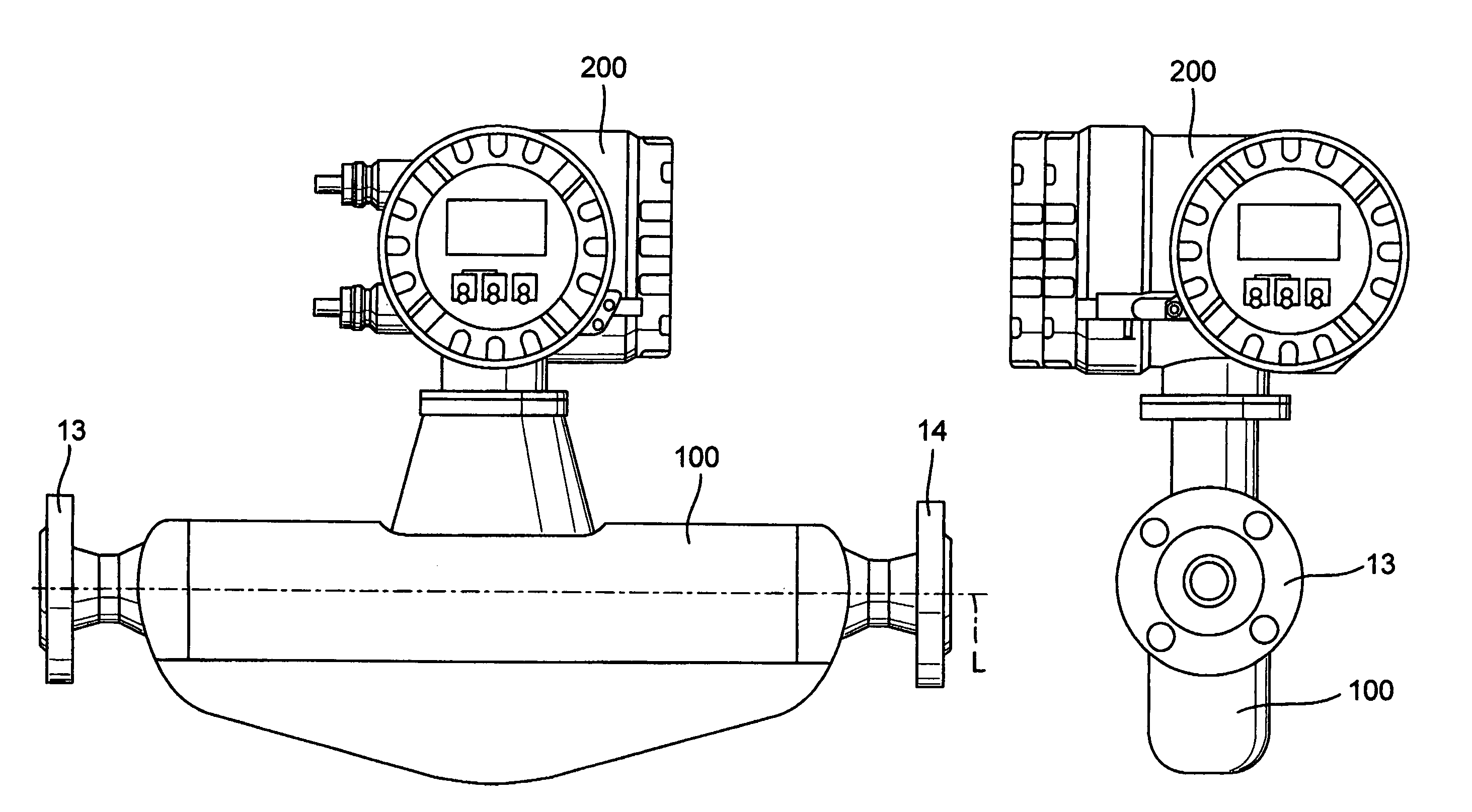
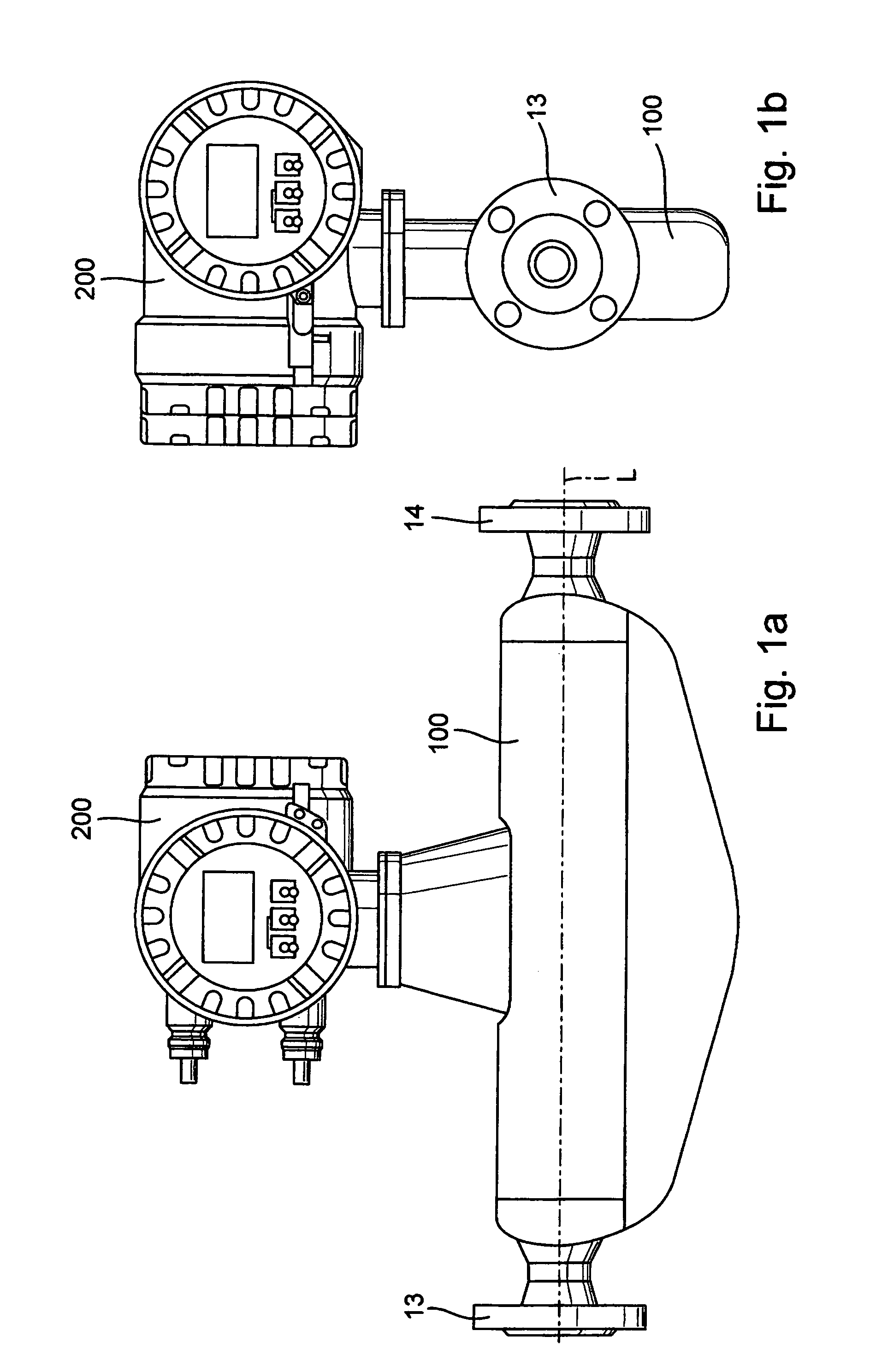
[0047]Shown in FIGS. 1a, b is an inline measuring device, for example, one embodied as a Coriolis mass flow measuring device, density measuring device, viscosity measuring device, or the like, installable into a pipeline, for example, a process line of an industrial plant. The inline measuring device serves for measuring and / or monitoring at least one parameter, for example, a mass flow, a density, viscosity, etc., of a medium flowing in a pipeline. The inline measuring device include...


PUM


Abstract

A measuring transducer includes a transducer housing, as well as an internal part arranged in the transducer housing. The internal part includes at least one curved measuring tube vibrating, at least at times, during operation and serving for conveying the medium, as well as a counteroscillator affixed to the measuring tube on the inlet-side, accompanied by formation of a coupling zone, and to the measuring tube on the outlet-side, accompanied by the formation of a coupling zone. The internal part is held oscillatably in the transducer housing, at least by means of two connecting tube pieces, via which the measuring tube communicates during operation with the pipeline and which are so oriented with respect to one another, as well as with respect to an imaginary longitudinal axis of the measuring transducer, that the internal part can move during operation in the manner of a pendulum about the longitudinal axis. The measuring tube and the counteroscillator are additionally so embodied and so oriented with respect to one another that both a center of mass spaced from the imaginary longitudinal axis of the measuring tube, as well as also a center of mass of the counteroscillator spaced from the imaginary longitudinal axis, lie in a common region of the measuring transducer spanned by the imaginary longitudinal axis and the measuring tube, and that the center of mass of the measuring tube is spaced farther from the longitudinal axis than the center of mass of the counteroscillator.

Description

[0001]This application is a nonprovisional of U.S. Provisional Application 60 / 752,372 filed on Dec. 22, 2005 and U.S. Provisional Application 60 / 752,374 filed on Dec. 22, 2005 and which claims the benefit of German application numbers 102005062007.8 filed on Dec. 22, 2005 and 102005062004.3 filed on Dec. 22, 2005.FIELD OF THE INVENTION[0002]The invention relates to a measuring transducer of vibration-type, especially one for use in a Coriolis mass flow meter.BACKGROUND OF THE INVENTION[0003]For determining a mass flow of a medium flowing in a pipeline, especially a liquid or other fluid, often such measuring devices are used which, by means of a measuring transducer of vibration-type and a control and evaluation electronics connected thereto, effect in the fluid Coriolis forces and, derived from these forces, produce a measurement signal representing mass flow. Such measuring transducers, especially also their use in Coriolis mass flow meters, have been known already for a long time...

Claims


Application Information

Patent Timeline
Patent Type & Authority Patents(United States)
IPC IPC(8): G01F1/84
CPCG01F1/8409G01F1/8413G01F1/8418G01F1/8477G01N11/02
Inventor BITTO, ENNIOSCHUTZE, CHRISTIANANKLIN-IMHOF, MARTINHUBER, CHRISTOFMUNDSCHIN, DIETERLAMBRIGGER, MICHAEL
Owner ENDRESS HAUSER FLOWTEC AG
Why Eureka
Try Eureka