Mechanical locking differential lockout mechanism

a technology of mechanical locking differential and lockout mechanism, which is applied in the direction of mechanical equipment, gearing, transportation and packaging, etc., can solve the problems of unsatisfactory performance of conventional locking differential

Active Publication Date: 2008-04-22
EATON INTELLIGENT POWER LTD
View PDF4 Cites 15 Cited by
  • Summary
  • Abstract
  • Description
  • Claims
  • Application Information

AI Technical Summary

Benefits of technology

[0005]Accordingly, it is an object of the present invention to provide an improved differential gear mechanism, of the “mechanical locker” type, in which it is possible to, in some manner, control operation of the mechanical device that normally initiates engagement of the differential clutch, wherein such control is not dependent on only the normal mode of operation of the mechanical device.
[0006]It is a more specific object of the present invention to provide such an improved differential gear mechanism in which it is possible to “lock-out” or to prevent the operation of, a flyweight mechanism which reacts to the speed difference between the two differential side gears and initiates engagement of the differential clutch.

Problems solved by technology

One situation that has been observed, in which the conventional locking differential does not perform in a satisfactory manner, is when a vehicle equipped with a mechanical locking differential is operating in a condition in which “spin-out” of one of the driving wheels is inherent.

Method used


Image

  • Mechanical locking differential lockout mechanism
  • Mechanical locking differential lockout mechanism
  • Mechanical locking differential lockout mechanism

Examples


Embodiment Construction

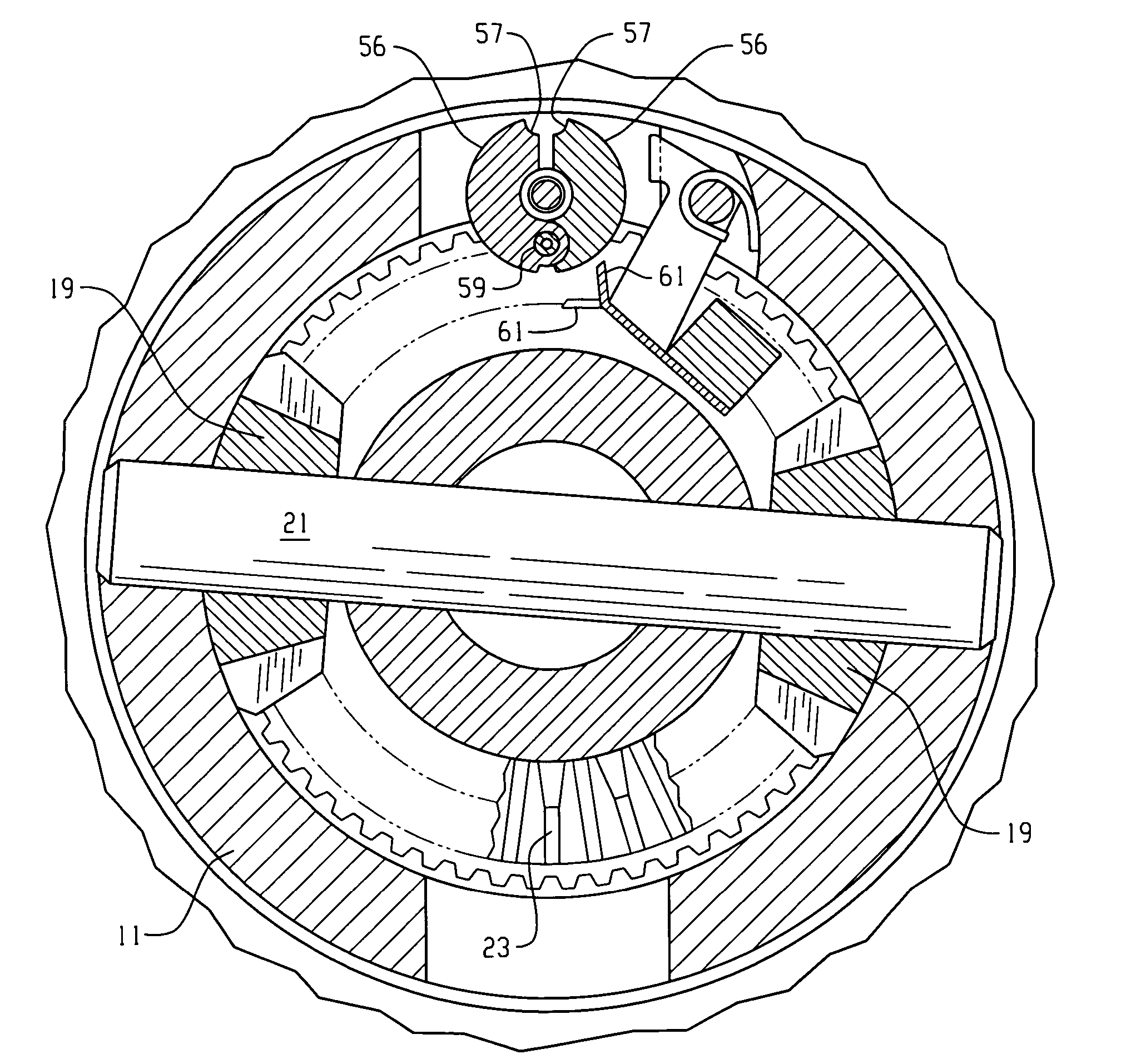
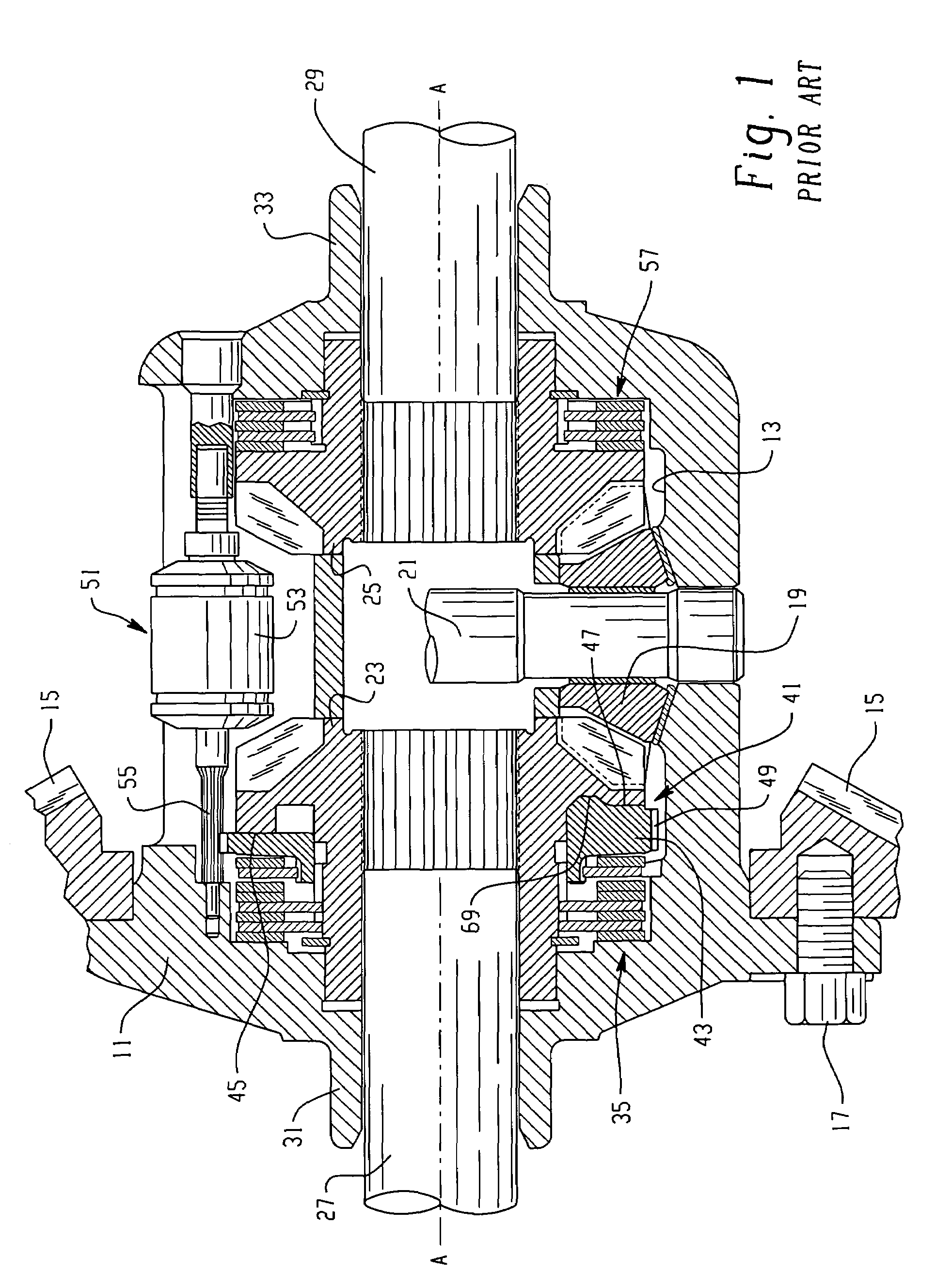
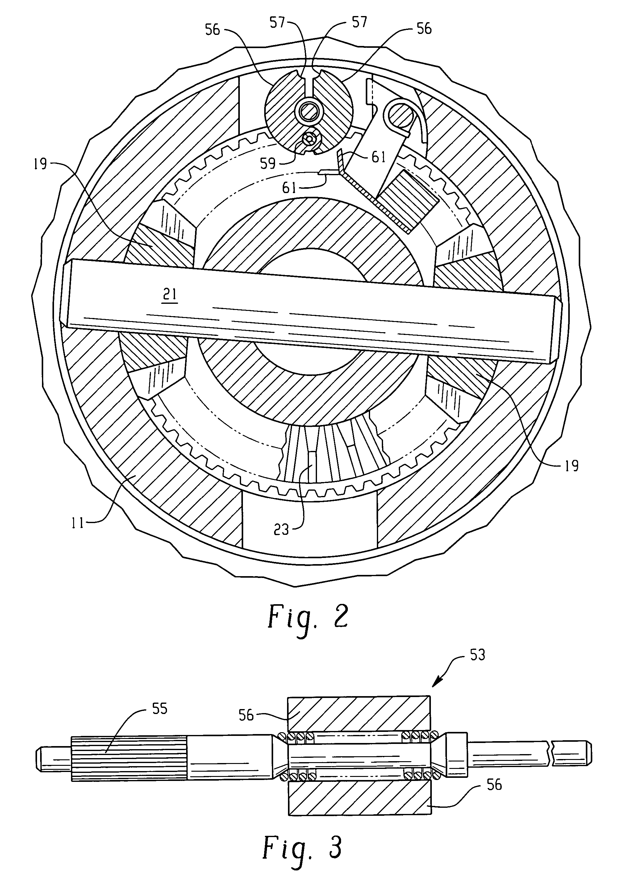
[0022]Referring now to the drawings, which are not intended to limit the invention, FIG. 1 is an axial cross-section of a locking differential gear mechanism of the type that may advantageously utilize the present invention. The overall construction and operation of the locking differential shown in FIG. 1 is already well known to those skilled in the art, and is illustrated and described in greater detail in the above-incorporated patents. The differential gear mechanism as shown in FIG. 1 (“Prior Art”) includes a gear case 11 that defines therein a gear chamber, generally designated 13. Torque input to the locking differential is typically by means of an input gear 15 (shown only in fragmentary view in FIG. 1). The input gear 15 (also referred to as a “ring gear”) is intended to be in toothed engagement with an input pinion gear (not shown in FIG. 1), which receives input drive torque from the vehicle driveline. The input gear 15 may be attached to the gear case 11 by means of a p...


PUM


Abstract

An improved differential gear mechanism is characterized by a lockout mechanism (63) operably associated with a flyweight mechanism (53) and including a lockout member (65, 101) positionable, in response to an input signal, in a normal condition and a lockout condition. In the normal condition, the lockout member (65, 101) permits a flyweight stop surface (57) to move from the retracted position to the extended position. In the lockout condition, the lockout member (65, 101) prevents the flyweight stop surface (57) from moving from the retracted position to the extended position.

Description

BACKGROUND OF THE DISCLOSURE[0001]The present invention relates to differential gear mechanisms, and more particularly, to such mechanisms of the type commonly referred to as “locking differentials”. More specifically, the present invention relates to mechanisms of the type also referred to as “mechanical lockers”, i.e., locking differentials in which the locking function occurs in response to the operation of a mechanical device, as opposed to hydraulic actuation or electromagnetic actuation.[0002]A conventional locking differential made by the assignee of the present invention utilizes a flyweight mechanism to initiate the lock-up of the differential clutch, wherein the flyweight mechanism then retards rotation of the cam plate relative to the differential input (i.e., the ring gear and differential case). Locking differentials of the type that utilize a flyweight mechanism to initiate clutch engagement are now well known, and may be made in accordance with the teachings of any on...

Claims


Application Information

Patent Timeline
Patent Type & Authority Patents(United States)
IPC IPC(8): F16H48/06F16H48/30
CPCF16H48/08F16H48/22F16H48/24F16H48/34F16H48/30F16H2048/346F16H2048/201F16H2048/204
Inventor KYLE, ROBERT J.MORGENSAI, KEITH E.SAPE, THOMAS L.HEATWOLE, GREGORY L.
Owner EATON INTELLIGENT POWER LTD
Why Eureka
Try Eureka