Wire collision sensor system
a collision sensor and wire technology, applied in the direction of roofs, pedestrian/occupant safety arrangements, vehicular safety arrangements, etc., can solve the problems of deteriorating sensing accuracy and disadvantage of sensing latency
- Summary
- Abstract
- Description
- Claims
- Application Information
AI Technical Summary
Benefits of technology
Problems solved by technology
Method used
Image
Examples
first embodiment
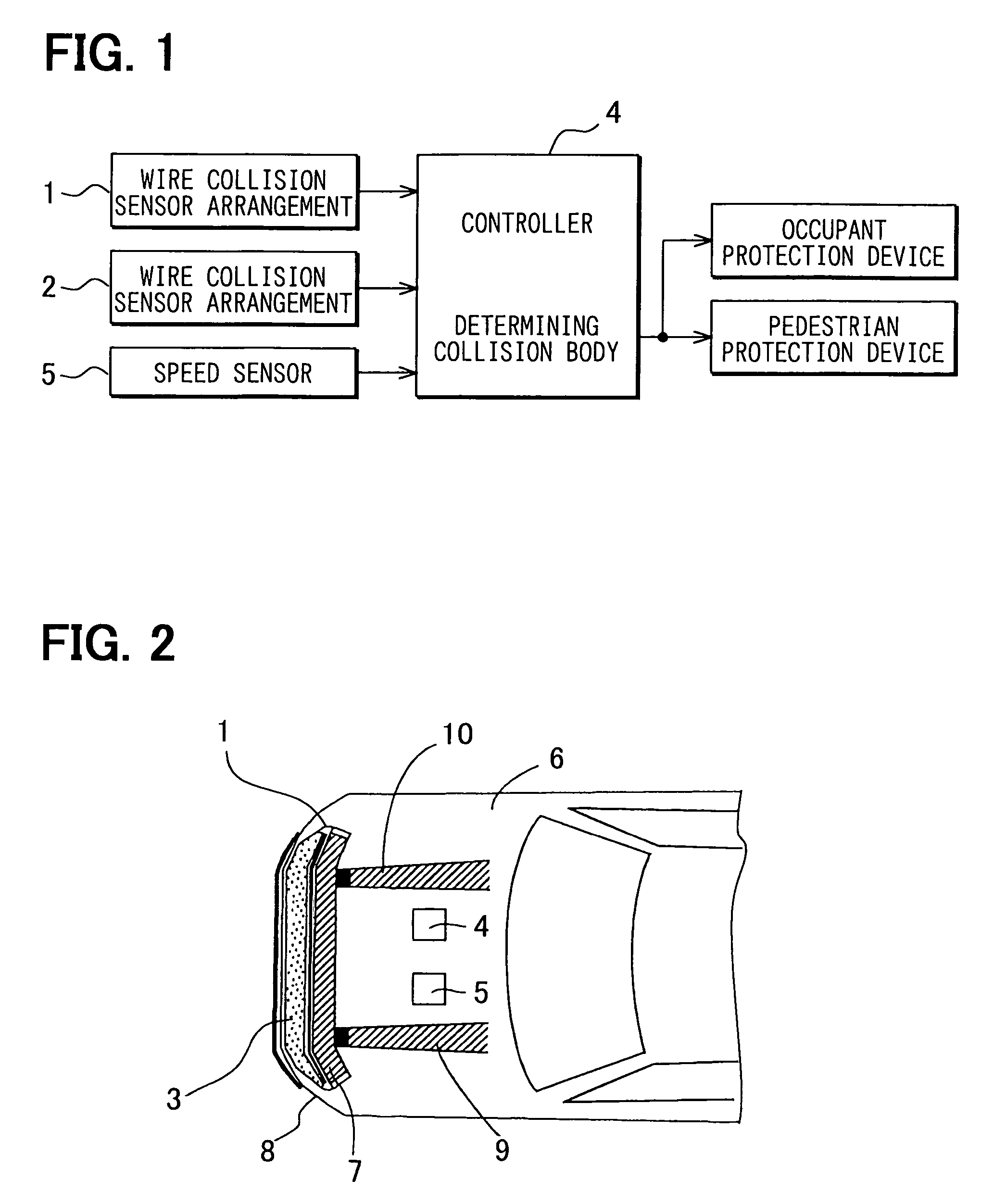
[0015]A wire collision sensor system for a vehicle of a first embodiment will be described with reference to a block diagram shown in FIG. 1 and a schematic plan view shown in FIG. 2. A front direction according to the present embodiment is a driving direction of the vehicle. A widthwise direction according to the present embodiment is a transverse direction of the vehicle.
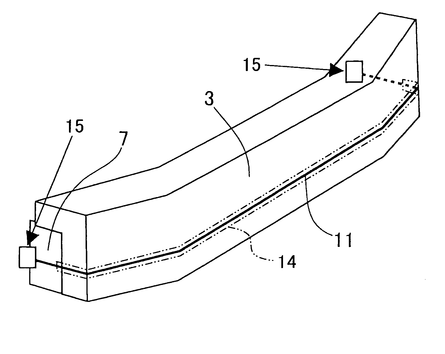
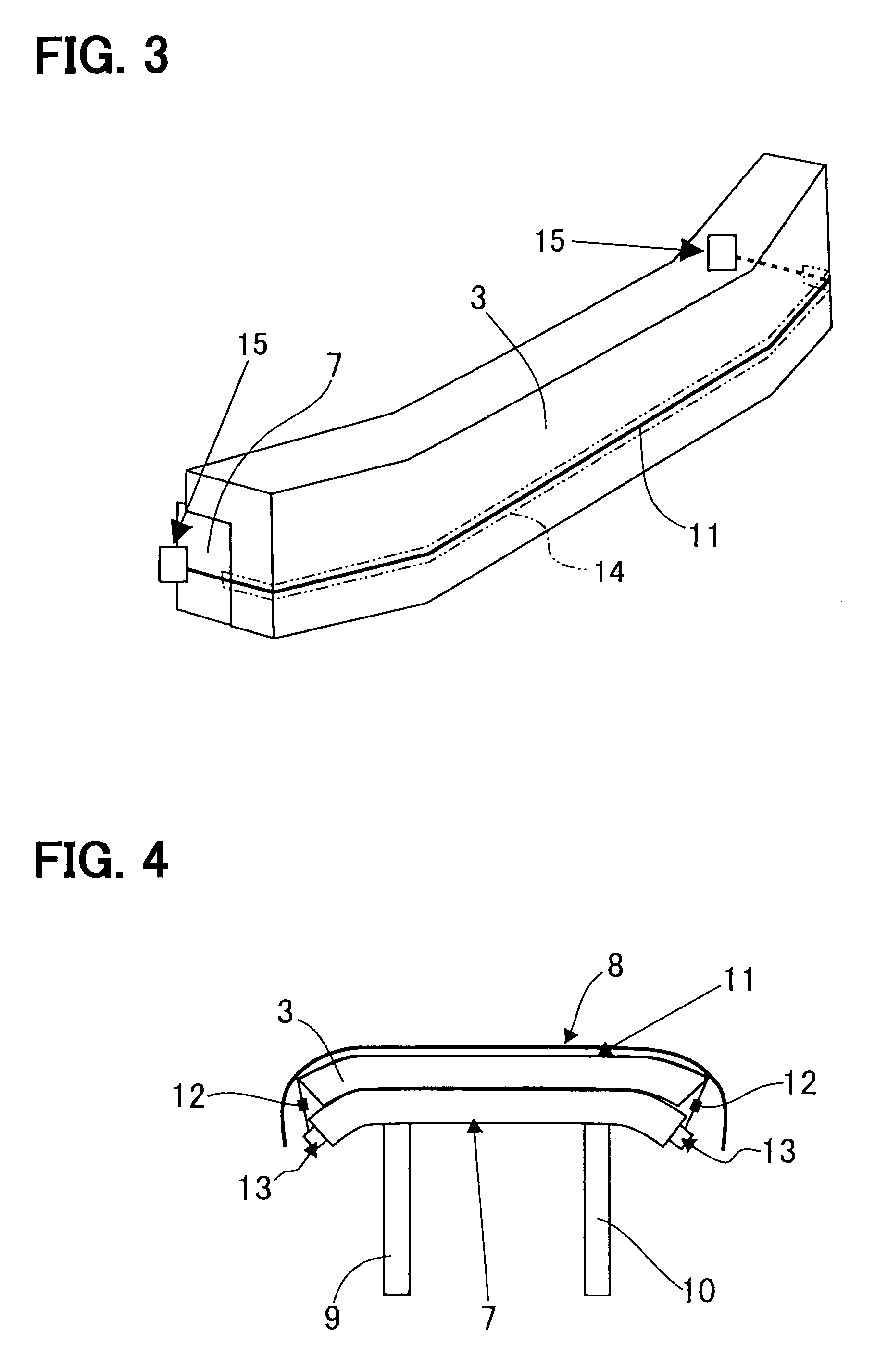
[0016]Numerals 1 and 2 are wire collision sensor arrangements, a numeral 3 is a bumper absorber, a numeral 4 is a controller (a signal processing unit), a numeral 5 is a speed sensor, a numeral 6 is a vehicle body, a numeral 7 is a bumper reinforcement, a numeral 8 is a bumper cover and numerals 9 and 10 are side members. The side members 9, 10 are structural members, which are arranged at a predetermined interval at a bottom part of the vehicle and extend in a longitudinal direction of the vehicle. The bumper reinforcement 7 is a structural member, which is fixed horizontally with front ends of the side members 9...
second embodiment
[0033]In a second embodiment, similar components of a wire collision sensor system, which are similar to the components of the wire collision sensor system of the first embodiment, will be indicated by the same numerals.
[0034]The second embodiment is characterized by supporting the resin thread 11 of the collision sensor system 1 in a back surface of the bumper cover 8. The bumper cover 8 includes projection members 81, which are arranged at predetermined intervals, and slidably support the resin thread 11. Each projection member 81 is formed into an L-shaped body, which defines a groove that opens upward. The groove supports the resin thread 11. The projection member 81 may be designed to have a hole, which supports the resin thread 11, instead of the groove. This brings an equivalent effect with the first embodiment. Also, the projection members 81, which are arranged at the predetermined intervals for slidably supporting the resin thread 11, may be supported by the bumper absorbe...
PUM
 Abstract
Description
Claims
Application Information
 - R&D
- Intellectual Property
- Life Sciences
- Materials
- Tech Scout
- Unparalleled Data Quality
- Higher Quality Content
- 60% Fewer Hallucinations
Browse by: Latest US Patents, China's latest patents, Technical Efficacy Thesaurus, Application Domain, Technology Topic, Popular Technical Reports.
© 2025 PatSnap. All rights reserved.Legal|Privacy policy|Modern Slavery Act Transparency Statement|Sitemap|About US| Contact US: help@patsnap.com


