QPSK light modulator

a light modulator and quadrature phase shift technology, applied in optics, instruments, electrical equipment, etc., can solve the problems of deteriorating communication quality, error rate, and difference between amplitudes of optical outputs i and q, and achieve the effect of stable iq amplitude ratio

Inactive Publication Date: 2008-04-29
YOKOGAWA ELECTRIC CORP
View PDF5 Cites 28 Cited by
  • Summary
  • Abstract
  • Description
  • Claims
  • Application Information

AI Technical Summary

Benefits of technology

[0018]The present invention provides a light transmitter that provides a stable IQ amplitude ratio relative to the characteristic change of a modulating system.

Problems solved by technology

Accordingly, a problem arises in that a difference is generated between the amplitudes of the optical outputs I and Q.
As described above, when the constellation deteriorates, it becomes harder for a receiving side (not shown in the drawing) to separate the four symbol positions, and the error rate is worsened and communication quality deteriorates.

Method used


Image

  • QPSK light modulator
  • QPSK light modulator
  • QPSK light modulator

Examples


Embodiment Construction

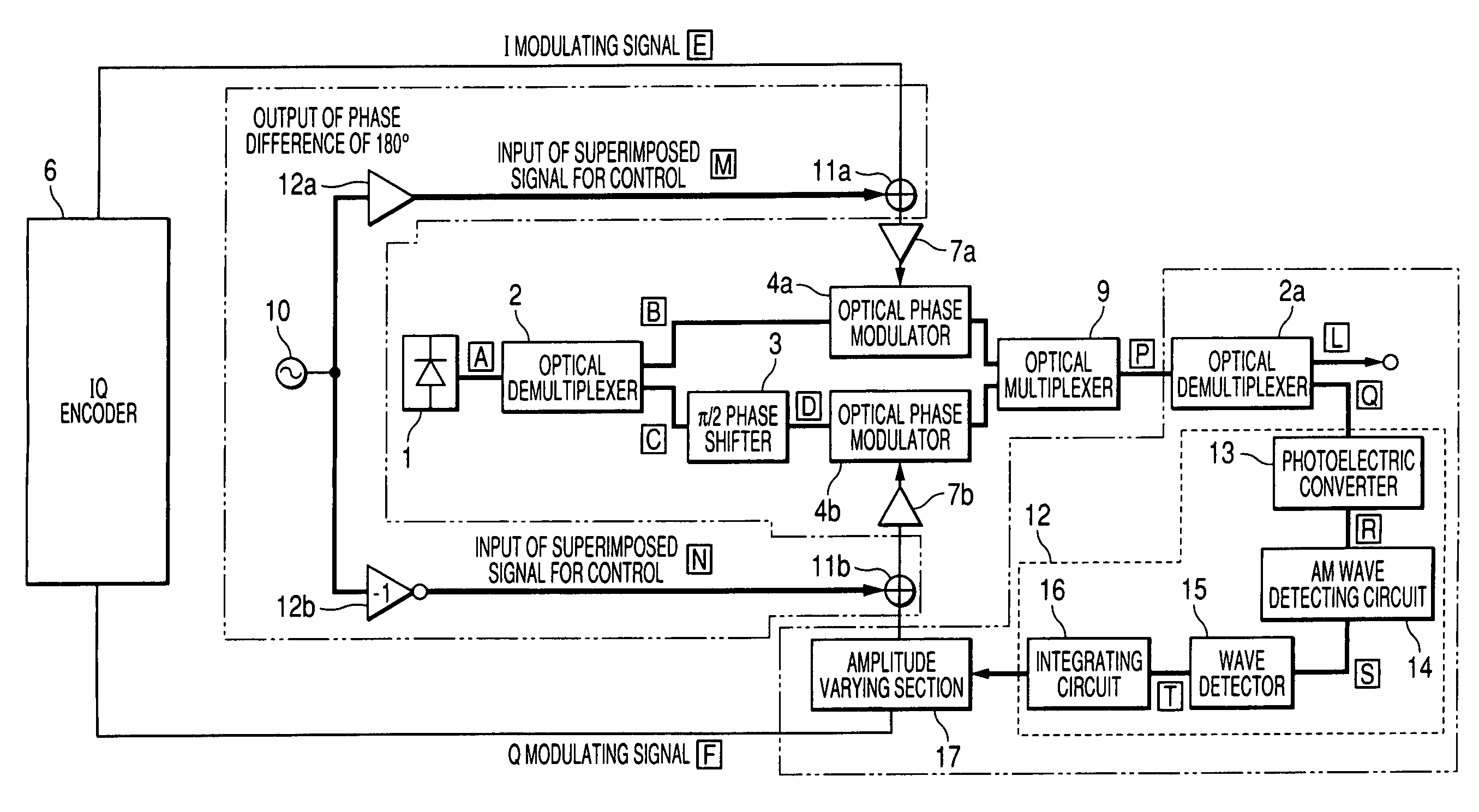
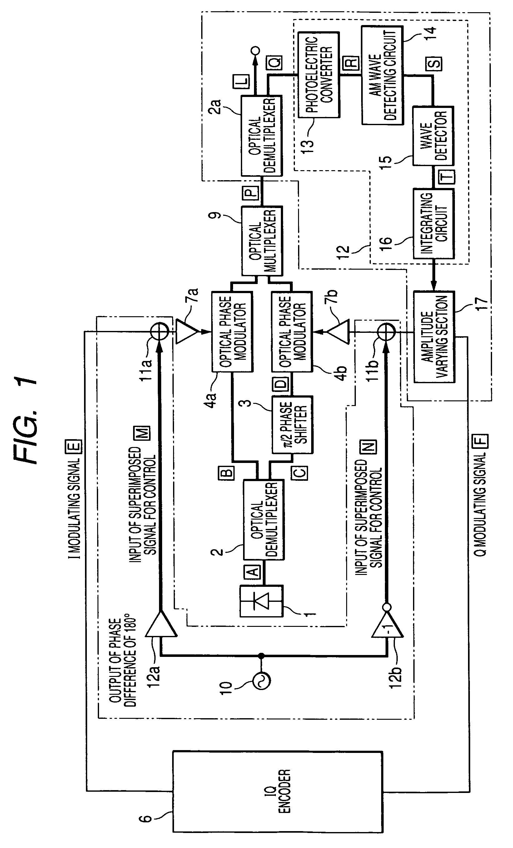
[0037]FIG. 1 is a block diagram of the main parts that show one example of an embodiment of the present invention. An explanation of the elements in FIG. 1 which are designated by the same reference numerals as those of the related example shown in FIG. 5 is omitted. Reference numeral 10 designates a low frequency signal generating section. Controlling superimposed signals generated by the low frequency signal generating section 10 are inputted to signal adders 11a and 11b provided front stage of drivers 7a and 7b, then added to an I modulating signal [E] and a Q modulating signal [F] and respectively inputted to optical phase modulators 4a and 4b through the drivers 7a and 7b.

[0038]The controlling superimposed signals are amplified by amplifiers 12a and 12b at front stages of signal adders 11a and 11b. The amplifier 12b has an inverter function so that its signals are outputted in a state that the phases are different from each other by 180°.

[0039]The outputs of optical phase modu...


PUM

PropertyMeasurementUnit
constant wavelengthaaaaaaaaaa
frequencyaaaaaaaaaa
constant phaseaaaaaaaaaa

Abstract

The present invention provides a light transmitter with a stable IQ amplitude ratio relative to the characteristic change of a modulating system. The QPSK light modulator of the present invention includes a laser light source for outputting light; an optical demultiplexer for inputting light and branching it in two directions; two optical phase modulators for inputting respectively one of the branched lights; a π / 2 phase shifter provided before or after one of the two optical phase modulators; an encoder for inputting I and Q signals into the optical phase modulators through drivers; and an optical multiplexer for synthesizing the outputs of the two optical phase modulators into a multiplexed, modulated light. The QPSK light modulator includes another optical demultiplexer after the optical multiplexer and a correcting section for correcting amplitude unbalance generated when light passes between the optical demultiplexers, by using output from the second optical demultiplexer.

Description

[0001]This application claims foreign priority based on Japanese Patent application No. 2005-186405, filed Jun. 27, 2005, the content of which is incorporated herein by reference in its entirety.BACKGROUND OF THE INVENTION[0002]1. Field of the Invention[0003]The present invention relates to a QPSK (Quadrature Phase Shift Keying) light transmitting section used in an optical communication system of a wavelength division multiplex (WDM) type and more particularly to a QPSK light modulator that compensates the amplitudes of an I component and a Q component of the optical output of a light modulating section forming the light transmitting section so that the amplitudes are equal.[0004]2. Description of the Related Art[0005]For a description of an optical communication system of the wavelength division multiplex (WDM) type using a QPSK light transmitting section, see JP-A-2004-516743.[0006]FIG. 5 is a block diagram of main parts showing one example of the QPSK light transmitting section ...

Claims


Application Information

Patent Timeline
Patent Type & Authority Patents(United States)
IPC IPC(8): G02F1/035H04B10/04H04B10/516H04B10/548H04B10/61
CPCH04B10/505H04B10/5055H04B10/50572H04B10/5561
Inventor TANIMURA, DAISUKE
Owner YOKOGAWA ELECTRIC CORP
Why Eureka
Try Eureka