Pumping device

a pumping device and pumping tube technology, applied in water cleaning, packaged goods type, separation processes, etc., can solve the problems of unfavorable environmental protection, unfavorable environmental protection, and complicated structure of oil pumping devices, so as to increase or decrease the internal pressure of the container

Active Publication Date: 2008-05-06
LIH YANN INDAL
View PDF12 Cites 34 Cited by
  • Summary
  • Abstract
  • Description
  • Claims
  • Application Information

AI Technical Summary

Problems solved by technology

This is not an efficient way for draining oil from the automobile engine and may cause undesired contamination to the surroundings.
However, such oil pumping devices have a complicated structure and can only be manually or pneumatically operated.
However, such as conventional device still suffers certain drawbacks that can be further improved.

Method used


Image

  • Pumping device
  • Pumping device
  • Pumping device

Examples


Embodiment Construction

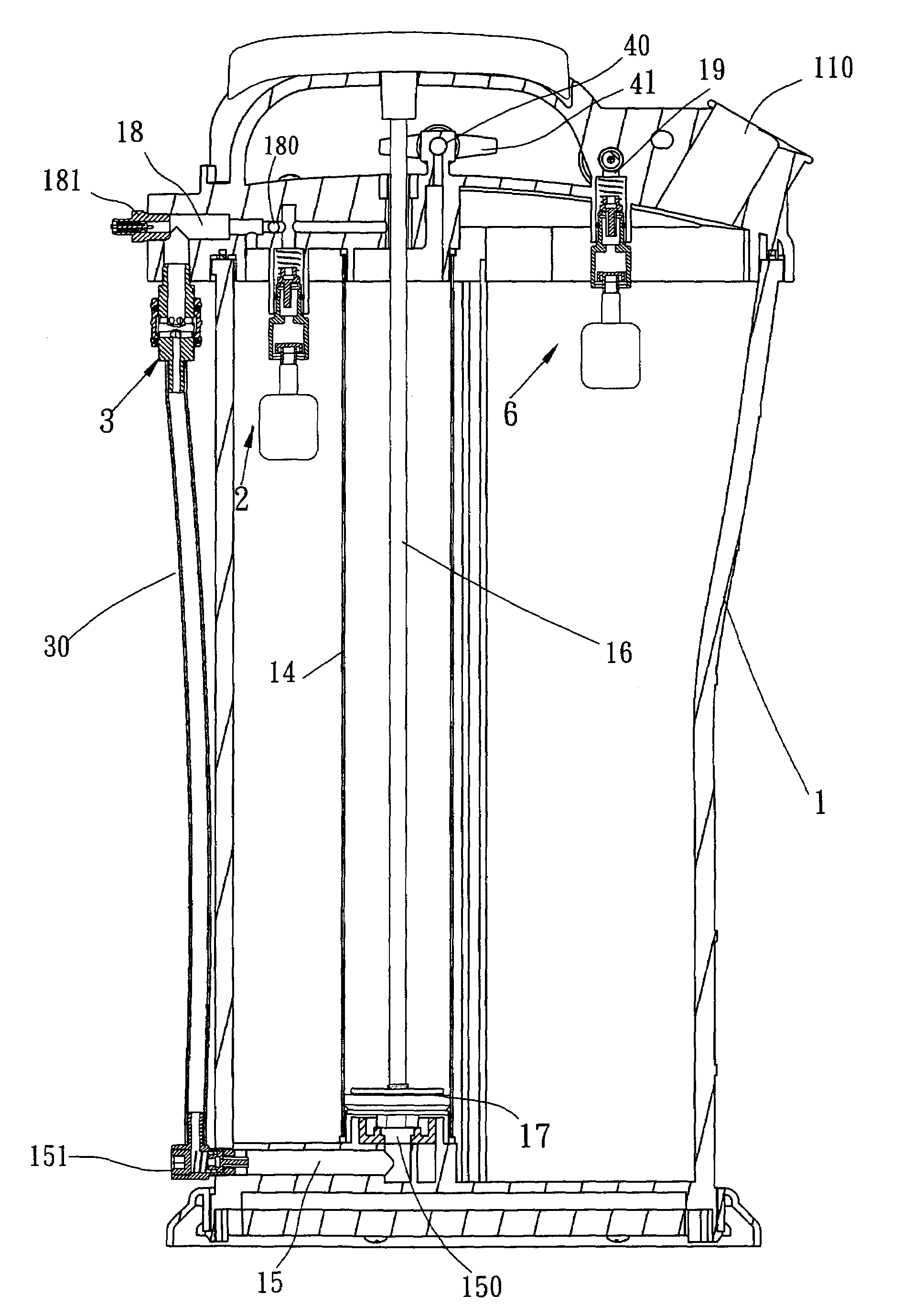
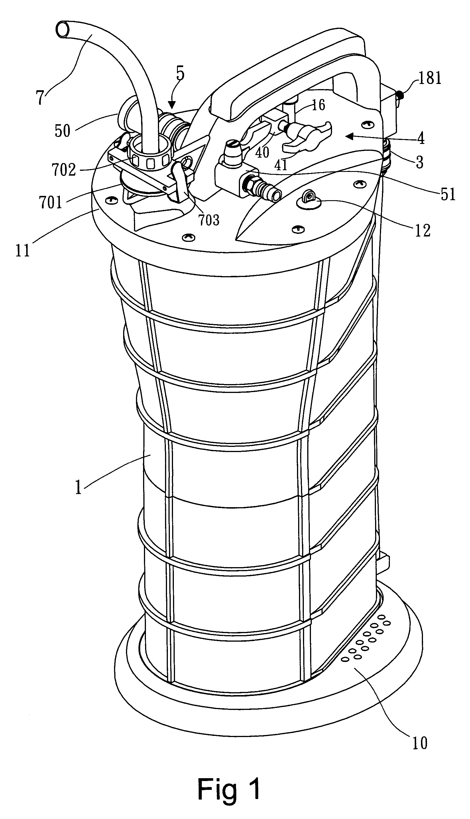
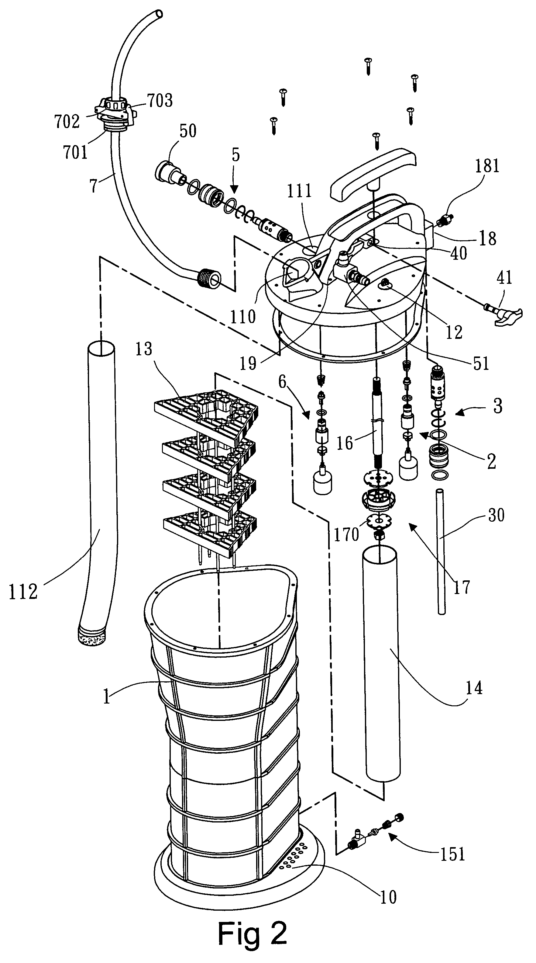
[0022]With reference to the drawings and in particular to FIGS. 1 and 2, a pumping device constructed in accordance with the present invention comprises a container body 1 having a bottom forming a base 10 that can be stepped on by a user's foot to fix the pumping device on a fixture surface during the operation of the pumping device. The container body 1 also has an open top to which a cover structure 11 is mounted.

[0023]Also referring to FIGS. 3A and 3B, the cover structure 11 has a size substantially corresponding to and thus closing the top opening of the container body 1. The cover structure 11 defines a through hole 120 that receives and retains a relief valve 12. The relief valve 12 comprises a plug-like body (not labeled) movably received in the hole 120 and having expanded top and bottom ends. A biasing element 121, such as a helical spring, is arranged between the expanded bottom end of the valve body 12 and a circumferential edge of the hole 120 of the cover structure 11 ...


PUM

PropertyMeasurementUnit
internal pressureaaaaaaaaaa
pressureaaaaaaaaaa
sizeaaaaaaaaaa

Abstract

A pumping device includes a container having a cover structure. A piston is movably received in the container and is manually operable. The cover structure has an air inlet valve and a slide switch, which, when properly set, allow air to be sucked into or expelled out of the container by the manual operation of the piston to increase or decrease the internal pressure of the container for oil suction and oil drainage. The pumping device also includes another slide switch, whereby when both slide switches are properly set, the internal pressure of the container is increased or decreased due to the supply of pressurized air from an external source and oil can be sucked into and drained out of the container accordingly.

Description

BACKGROUND OF THE INVENTION[0001]1. Field of the Invention[0002]The present invention relates generally to a pumping device, and in particular to a pumping device that can be manually or pneumatically operated to selectively suck liquid into a container and to drain the liquid out of the container.[0003]2. The Related Art[0004]Replacement and / or replenishment of oil is one of the most important jobs for maintenance and repairing of automobiles. Often, the oil is drained from the oil pan by simply removing the oil drain plug that blocks a drain hole formed in the bottom of the oil pan whereby oil is allowed to freely flow out of the drain hole. This is not an efficient way for draining oil from the automobile engine and may cause undesired contamination to the surroundings. Oil pumping devices or oil draining devices are available. However, such oil pumping devices have a complicated structure and can only be manually or pneumatically operated. In Taiwan Patent Application No. 902158...

Claims


Application Information

Patent Timeline
Patent Type & Authority Patents(United States)
IPC IPC(8): B65B1/04B65B31/04F04B23/14F04F1/06
CPCF04B33/00F04F1/02F04F1/06F04F3/00
Inventor LIAO, PO-LIN
Owner LIH YANN INDAL
Why Eureka
Try Eureka