Ultrasonic diagnostic apparatus with automatic marking

a diagnostic apparatus and ultrasonic technology, applied in the field of ultrasonic diagnostic equipment, can solve problems such as low operational efficiency, and achieve the effect of improving operational efficiency and relieving operator of awkward operations

Inactive Publication Date: 2008-05-06
GE MEDICAL SYST GLOBAL TECH CO LLC
View PDF23 Cites 4 Cited by
  • Summary
  • Abstract
  • Description
  • Claims
  • Application Information

AI Technical Summary

Benefits of technology

[0012]Therefore, it is an object of the present invention to provide an ultrasonic diagnostic apparatus which is capable of relieving the operator of awkward operations and improving the operational efficiency.
[0015]The inventive ultrasonic diagnostic apparatus is capable of relieving the operator's awkward operations and improving the operational efficiency. Further objects and advantages of the present invention will be apparent from the following description of the preferred embodiments of the invention as illustrated in the accompanying drawings.

Problems solved by technology

Since the operator performs awkward operations such as fast feeding the frames forwardly and reversely repeatedly in order to set the necessary range, the operator has to bear a great burden, resulting in a low operational efficiency.

Method used


Image

  • Ultrasonic diagnostic apparatus with automatic marking
  • Ultrasonic diagnostic apparatus with automatic marking
  • Ultrasonic diagnostic apparatus with automatic marking

Examples


Embodiment Construction

[0020]An embodiment of this invention will be explained with reference to the drawings.

[0021]FIG. 1 shows by block diagram the overall arrangement of the ultrasonic diagnostic apparatus based on an embodiment of this invention.

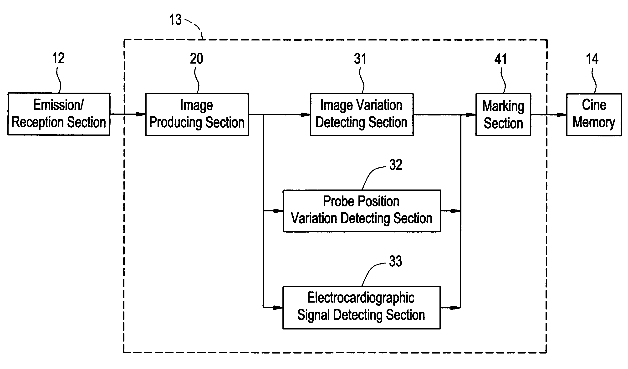
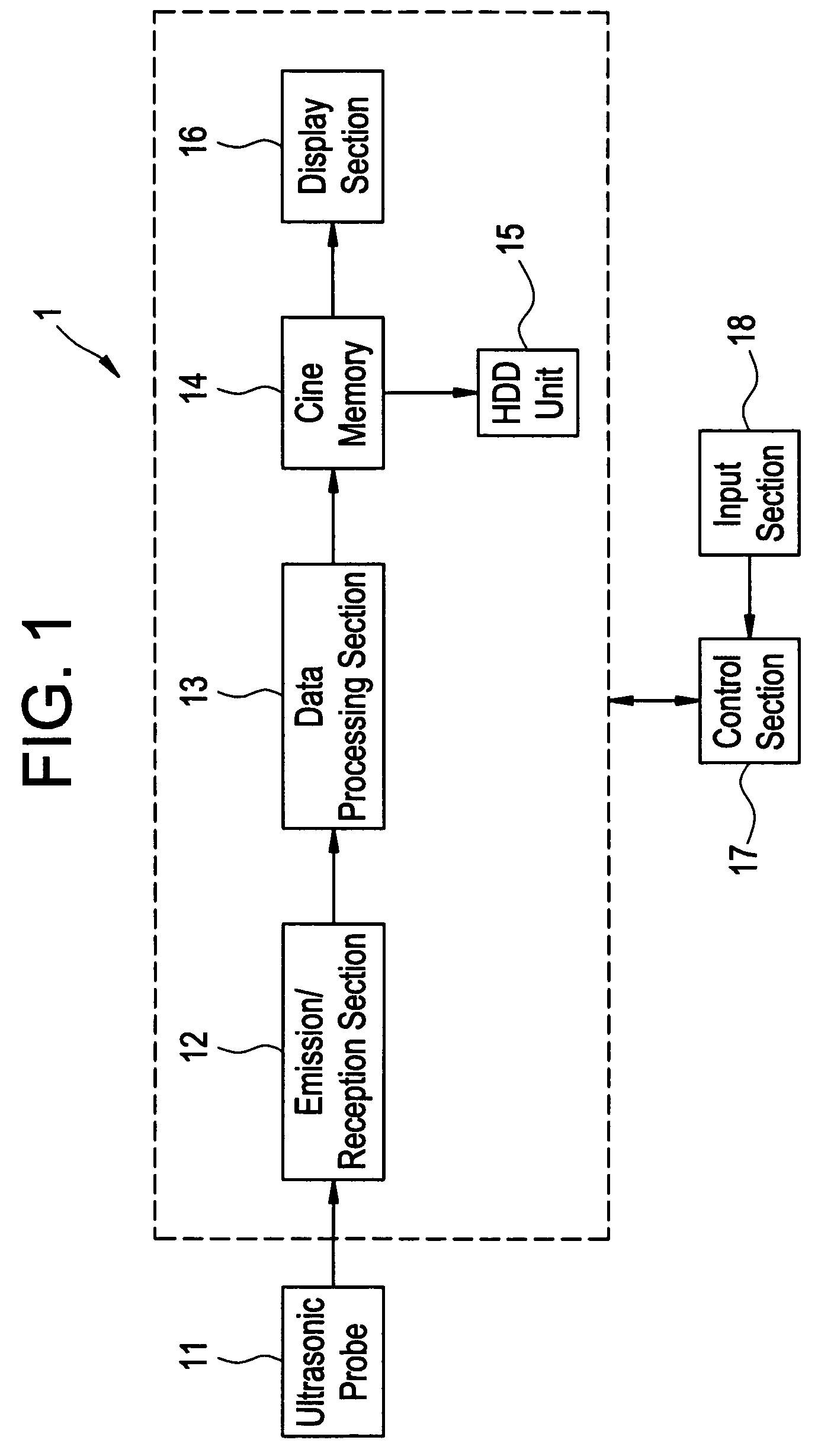
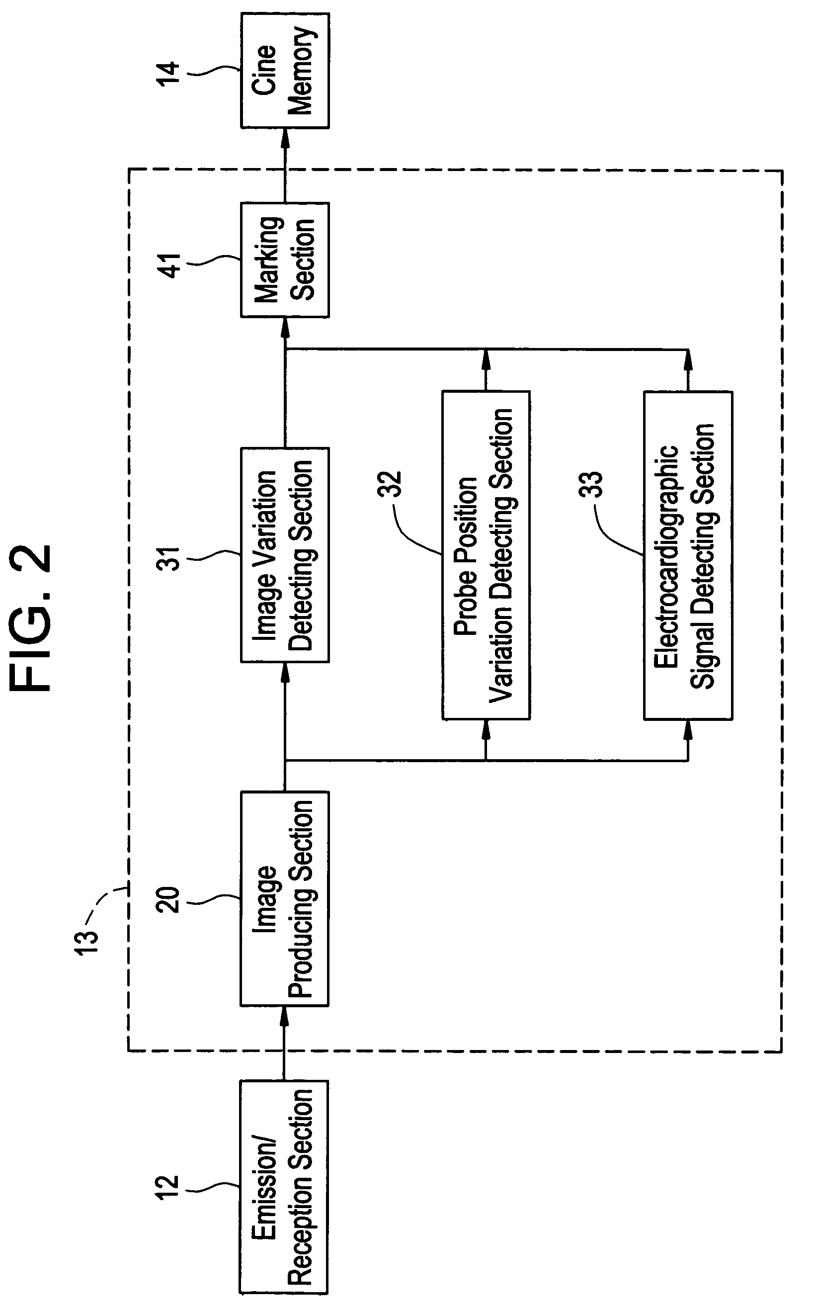
[0022]The ultrasonic diagnostic apparatus 1 includes an ultrasonic probe 11, an ultrasonic wave emission / reception section 12, a data processing section 13, a cine memory 14, a HDD unit 15, a display section 16, a control section 17, and an input section 18.

[0023]The cine memory 14 of this embodiment is a derivative of first memory means of this invention. The HDD unit of this embodiment is a derivative of second memory means of this invention. The display section 16 of this embodiment is a derivative of display means of this invention. The input section 18 of this embodiment is a derivative of input means of this invention.

[0024]The ultrasonic probe 11 includes an array of vibration elements (not shown). Each vibration element is formed of piezoelectric mater...


PUM


Abstract

An ultrasonic diagnostic apparatus includes an image producing section which produces images of time-serial frames of an inspection subject based on echoes of ultrasonic waves emitted to the subject, a marking section which marks certain frame images among the frame images produced by the image producing section, and a cine memory which memorizes data of the frame images produced by the image producing section and the time-serial positions of the frame images marked by the marking section.

Description

CROSS REFERENCE TO RELATED APPLICATIONS[0001]This application claims the benefit of Japanese Application No. 2003-413164 filed Dec. 11, 2003.BACKGROUND OF THE INVENTION[0002]The present invention relates to an ultrasonic diagnostic apparatus.[0003]The ultrasonic diagnostic apparatus is known to used for displaying tomographic images (B-mode images) of an inspection subject by using ultrasonic waves. The ultrasonic diagnostic apparatus, which is capable of readily producing tomographic images on a real-time basis, is used extensively in the medical field for the inspection of a fetus, a heart, etc.[0004]The ultrasonic diagnostic apparatus has various operation modes including B mode, M mode, and D mode. The B mode is mainly used for tomographic imaging of stationary organs of the inspection subject. The M mode, which displays a sonic line of time-serial B-mode images, is used for viewing the motion of a moving part such as a valve of a heart. The D mode, which is based on the Doppler...

Claims


Application Information

Patent Timeline
Patent Type & Authority Patents(United States)
IPC IPC(8): A61B8/00A61B5/352A61B8/08A61B8/14
CPCA61B8/461A61B8/14A61B5/0456A61B8/0866A61B8/466A61B5/352A61B8/00
Inventor KATO, SEI
Owner GE MEDICAL SYST GLOBAL TECH CO LLC
Why Eureka
Try Eureka