
Visualization device

a visualization device and working machine technology, applied in the field of visualization devices, can solve the problems of inability to completely determine, vehicle operators no longer directly integrated in the control process, and visualization systems reach their limits, so as to reduce the risk of accident and collision

Active Publication Date: 2016-09-06
CLAAS E SYST GMBH
View PDF14 Cites 0 Cited by
  • Summary
  • Abstract
  • Description
  • Claims
  • Application Information

AI Technical Summary

Benefits of technology

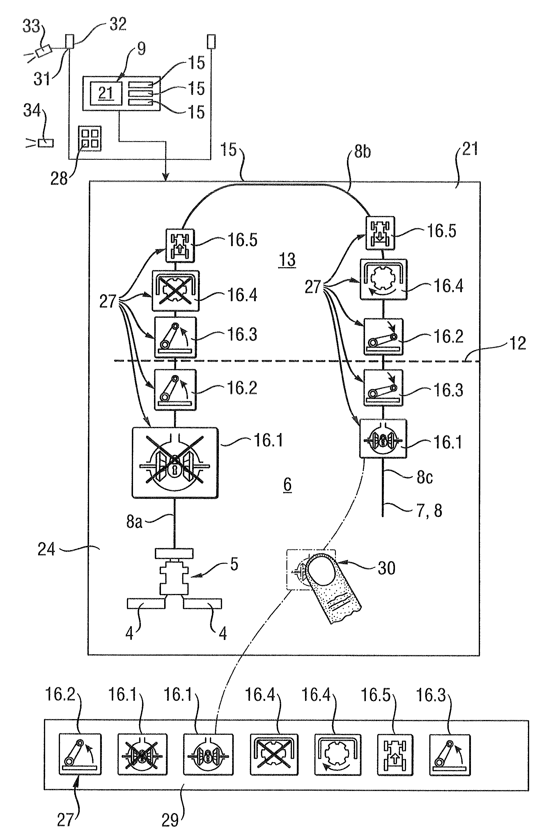
The invention is a system for controlling an agricultural working machine in the headland of a territory to be worked. The system uses a visualization device to display the driving path of the machine and the control operations being carried out by the operator. This allows the operator to see what control is currently being activated and which will be activated next. The system also makes it easy for the operator to switch between different control sequences. The machine is designed to allow for the quick and flexible movement of the working device or front harvesting attachment into a non-working position when leaving the headland and into a working position when entering the headland. The track-following system can operate in a GPS-based, camera-based, or sensor-based manner, using a laser sensor for example. This combination of technologies reduces the risks of accident and collision, allowing the operator to focus on the surrounding conditions during travel in the headland.

Problems solved by technology

Such visualization systems reach their limits, however, when the agricultural working machine works automatically determined, predefined driving routes.
In these cases, the vehicle operator is no longer directly integrated in the control process and is not entirely able to determine whether the control operations of the activated control sequence correspond with the momentary position of the vehicle.
In addition to limited operating comfort, however, such systems have the disadvantage in particular that there is no direct link between the control operations to be carried out and the momentary position of the agricultural vehicle on the territory to be worked.

Method used


Image

  • Visualization device
  • Visualization device
  • Visualization device

Examples


Embodiment Construction

[0024]The following is a detailed description of example embodiments of the invention depicted in the accompanying drawings. The example embodiments are presented in such detail as to clearly communicate the invention and are designed to make such embodiments obvious to a person of ordinary skill in the art. However, the amount of detail offered is not intended to limit the anticipated variations of embodiments; on the contrary, the intention is to cover all modifications, equivalents, and alternatives falling within the spirit and scope of the present invention, as defined by the appended claims.

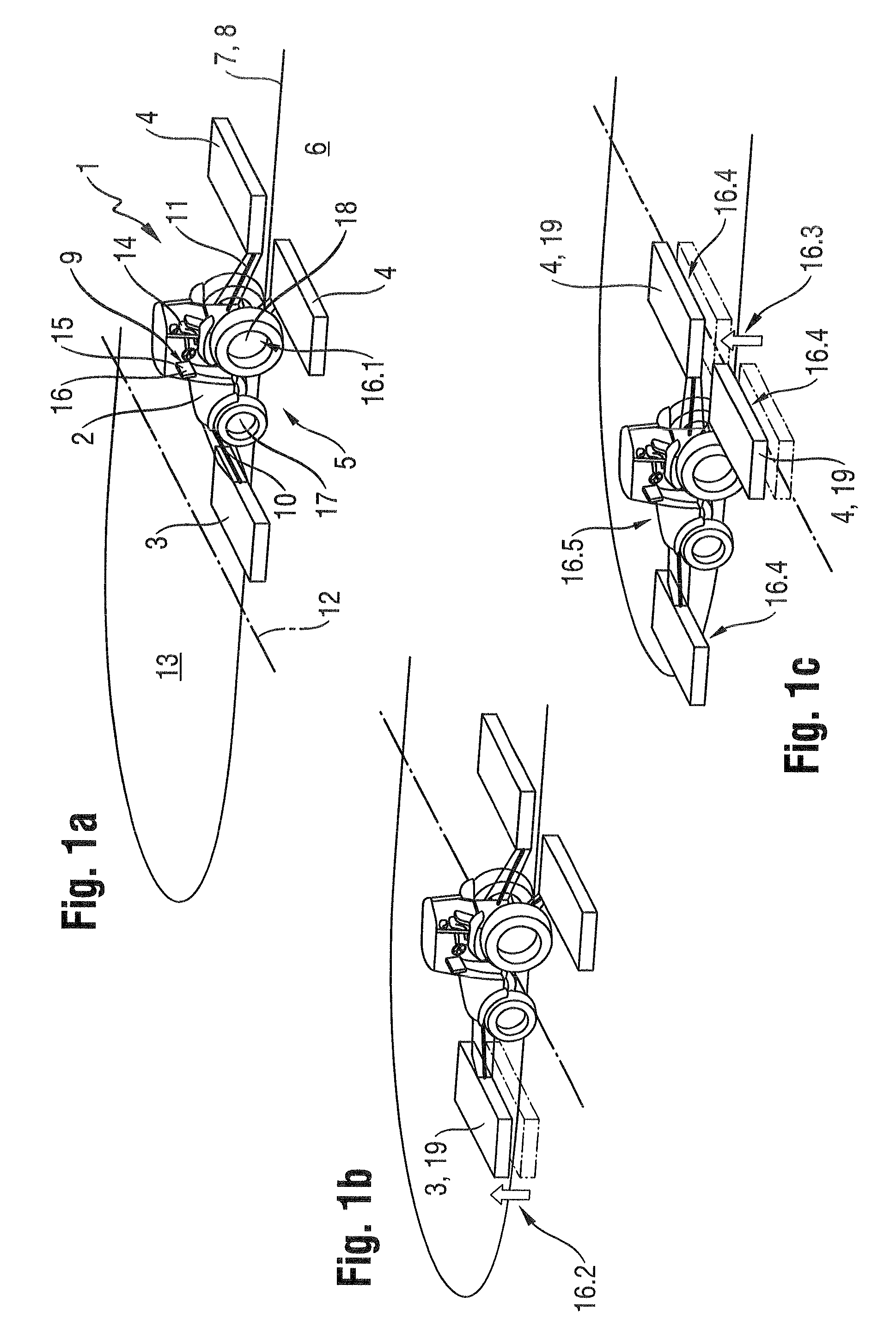
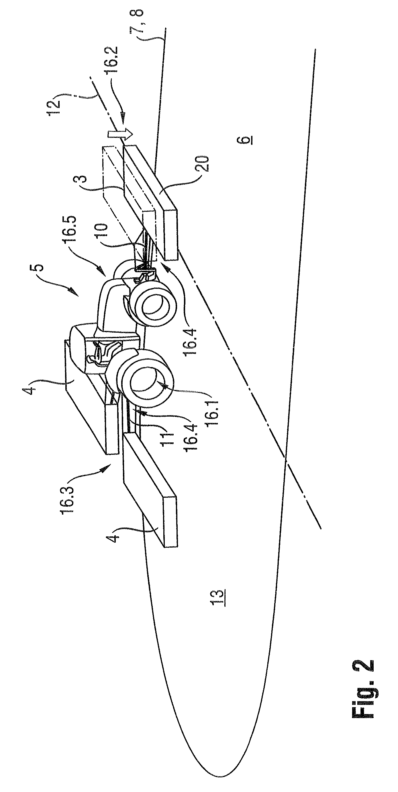
[0025]FIGS. 1a-c provide shows a schematic depiction of headland management 1 using the example of an agricultural working machine 5 designed as a tractor (2)—cutting mechanism (3, 4) combination. The agricultural working machine 5 moves on the territory 6 to be worked, i.e. the field, along driving paths 7 to be traveled. The driving paths 7 to be traveled are stored in a route plan 8 (to ...


PUM


Abstract

A device for visualizing control operations of an agricultural working machine includes a visualization device that visualizes at least one driving path to be traveled is assigned to the agricultural working machine. Control operations are stored in graphic images and the graphic images are displayed in the visualization device along the driving path to be traveled in the order in which they are carried out, to maintain an operator in an informed state with respect to the control processes that are taking place.

Description

CROSS-REFERENCE TO A RELATED APPLICATION[0001]The invention described and claimed hereinbelow is also described in German Patent Application DE 10 2011 054 630.8 filed on Oct. 20, 2011. This German Patent Application, subject matter of which is incorporated herein by reference, provides the basis for a claim of priority of invention under 35 U.S.C. 119(a)-(d).BACKGROUND OF THE INVENTION[0002]The invention relates to a device for visualizing control operations of an agricultural working machine.[0003]Document EP 0 820 688 made known a device for controlling actuating components of a utility vehicle, in which the driver of the utility vehicle can freely program a control sequence for the utility vehicle and activate the programmed control sequence by actuating a control button. Such systems have the advantage that complicated control operations can be automated, thereby relieving the driver of the working machine of complex control processes. Such automated control routines are used p...

Claims


Application Information

Patent Timeline
Patent Type & Authority Patents(United States)
IPC IPC(8): A01B79/00A01B69/00
CPCA01B79/005A01B69/001
Inventor MEYER ZU HELLIGEN, LARS PETERWEILAND, KALLE
Owner CLAAS E SYST GMBH
Learn More